Francis Pan is the Foreign Trade Manager of RAYMAX, with over 10 years of experience in sheet metal fabrication equipment and CNC machinery. He has worked closely with manufacturers worldwide on press brakes, fiber laser cutting machines, fiber laser welding machines, and practical production-oriented metal processing solutions.
Bending consistency depends on control over the material, tooling, machine, program, compensation, and inspection processes, rather than relying on repeated manual corrections by the operator. To improve bending consistency on a press brake, you must first identify the type of angle deviation or dimensional deviation:
If the entire bend is too large or too small, prioritize checking the material, V-die opening, and program parameters;
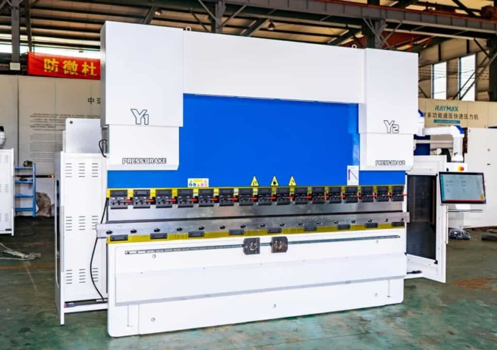
If there is angle inconsistency on the left and right sides, prioritize checking the Y1/Y2 synchronization status, tooling clamping, and material positioning methods;
If there is angle inconsistency at the center and both ends, prioritize checking the crowning system;
If the angle of the first part is within specification but the batch experiences angle drift, prioritize checking the material batch, tooling wear, hydraulic system stability, and process inspection;
If the angle is within specification but the flange length is inaccurate, prioritize checking the backgauge positioning and positioning reference.
To achieve truly stable bending quality, the following four criteria must be met simultaneously: consistent angle, consistent flange length, consistent straightness of the bend line, and consistent batch repeatability. A single piece with a qualified angle does not guarantee the entire batch is qualified.
This article will address diagnostic methods, machine condition, material properties, tooling selection, parameter settings, and inspection methods, analyzing key factors affecting bending quality one by one and providing corresponding solutions.
30-second diagnostic checklist
On-site observations
Priority check
What to check first
Corrective action
Angles along the entire bend line are either too large or too small
Parameter or springback issues
Material thickness, strength, V-die opening, bend depth
Correct material parameters and angle compensation values after trial bend verification
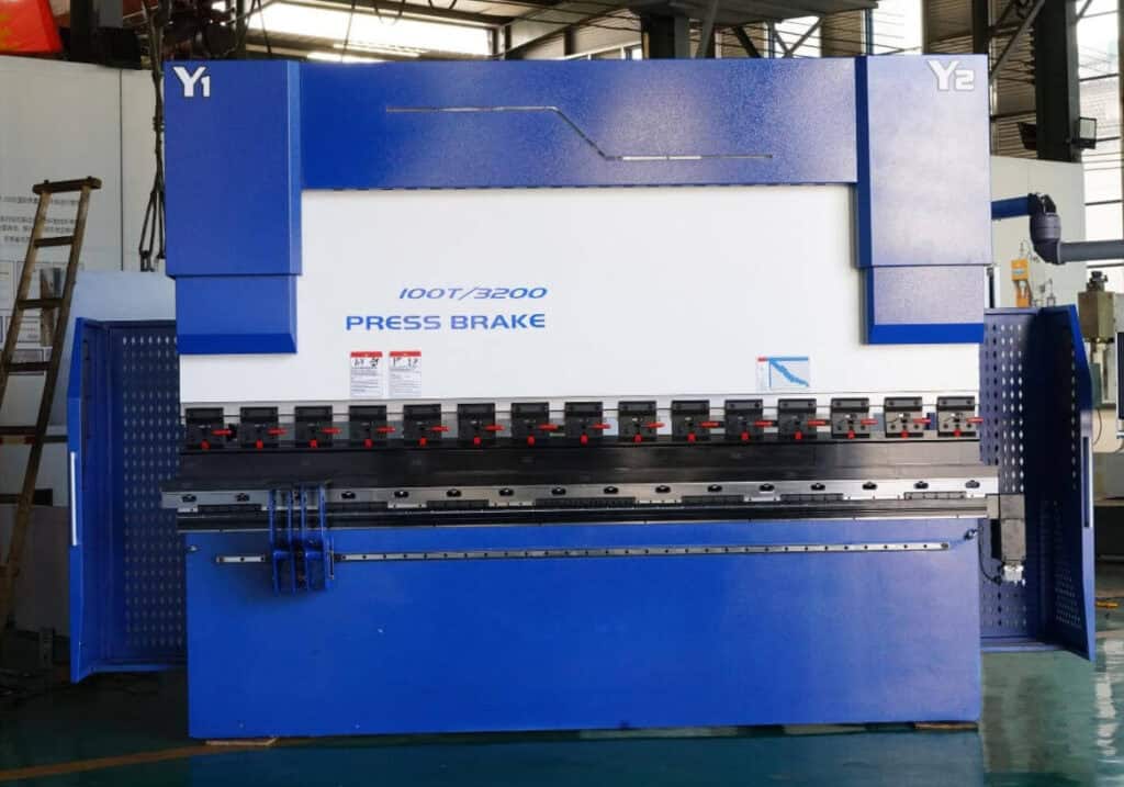
There is angle inconsistency on the left and right sides
Inconsistent force or Y1/Y2 synchronization deviation
Y1/Y2, punch and die alignment, clamping status, machine levelness
Perform calibration of Y1/Y2 synchronization, remount the tooling, and check the workpiece positioning method
Angles at the center differ from those at the ends
Deflection of long workpieces
Crowning settings, bend length, tonnage, force on the lower die
Adjust crowning compensation values, verify workpiece length and tooling assembly
The first part is acceptable, but deviations increase as production continues
Batch drift
Material batch, hydraulic oil temperature, tooling wear, sampling inspection frequency
Establish process inspection, record batch numbers and compensation values
Angles are within specifications but flange lengths are inconsistent
Backgauge issues
X-axis positioning, backgauge fingers (check for loosening), material positioning method
Check the repeatability of the backgauge positioning and operational movements
This refers to the ability to maintain a consistent angle on every workpiece after bending, under the same material, process, and tooling conditions.
It is primarily influenced by various factors, including material springback, variations in sheet thickness, the V-die opening, bending depth, Y1/Y2 synchronization accuracy, crowning, and the degree of tooling wear.
Angle consistency is the most intuitive indicator of bending quality, but it is not the only one. Focusing solely on angle may overlook many critical issues that lead to assembly failures.
Flange length consistency
This refers to the ability of the workpiece’s flange length to remain stable after each bending operation.
It is primarily affected by the following factors: the positioning accuracy of the backgauge’s X-axis, finger loosening, whether the workpiece is firmly against the backgauge fingers when positioned, whether there are burrs on the workpiece edges, whether the positioning reference changes during multi-pass bending, and whether the operator’s force and method of pushing the material are correct.
When encountering a situation where the angle is within specifications but assembly fails, prioritize checking the flange length, backgauge positioning, and the reference for multi-pass bending. Assembly failure is not necessarily due to an angle issue; it may result from cumulative dimensional deviations across various components.
Therefore, during troubleshooting, we should comprehensively consider factors such as dimensions, positioning, and reference points, rather than focusing solely on the angle.
Consistency of bend line straightness
This refers to the ability of a long workpiece to remain straight and stable along the entire bend line, without angle inconsistencies between the center and the two ends.
It is primarily influenced by the following factors: deflection of the ram and worktable under load, crowning system values, actual workpiece length, segmented tooling height, V-die opening, front support or sheet follower systems, and sagging due to the workpiece’s own weight.
The angle stability of long workpieces cannot be assessed by examining a single point; actual measurement data from at least multiple points—left, center, and right—must be considered.
Batch repeatability
This refers to the consistency in angle, flange length, and straightness between the first, 50th, and 500th parts produced.
It is primarily influenced by the following factors: variations in material batches, changes in hydraulic oil temperature, the degree of tooling wear, whether the program has been arbitrarily modified, the frequency of sampling inspections, process card records, and the consistency of operator movements.
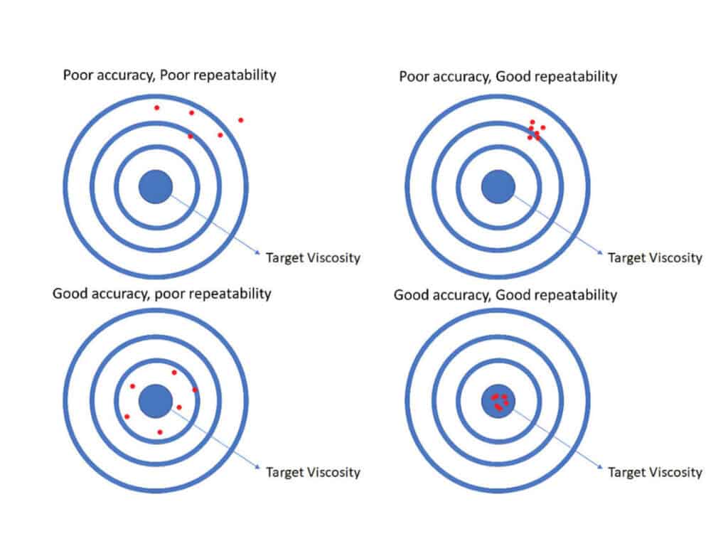
A qualified first part does not guarantee stable batch production; what we truly value when purchasing a press brake is the equipment’s long-term repeatability. If you want to understand the difference between repeatability and accuracy in press brake bending, read our guide on press brake repeatability vs accuracy.
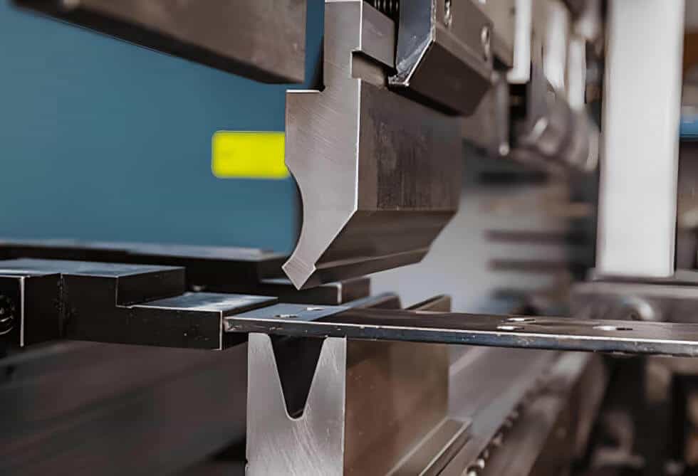
Press brake bending diagram
Identify the Type of Inconsistency Before Changing the Bending Program
The angle of the entire bend line is either too large or too small
Typical symptoms: The angle of an entire bend line is either consistently too large or too small; there is no significant difference in angle between the left and right ends, nor between the middle and the ends; the issue becomes more pronounced after switching to a new batch of material.
Primary causes: Program parameters do not match the actual sheet thickness; springback variation; incorrect V-die opening selection; incorrect bend depth settings; failure to update the material database in a timely manner; or directly reusing the springback compensation values from the previous batch of material.
On-site action: First, measure the actual current sheet thickness. Then, perform a first-piece trial bend using the current material. After the workpiece has fully unloaded, measure its actual angle. Adjust the springback compensation value based on the measured angle, and finally, enter the final compensation value into the program or process card.
Key takeaway: If the angles along an entire bend line are consistently too large or too small, do not immediately assume the machine is faulty; instead, first check the material properties, V-die opening, and program parameters.
Angle inconsistency between the left and right sides
Typical symptoms: The left-side angle is within specifications, but the right-side angle is too large or too small, or vice versa; there is a noticeable difference in angles between the left and right ends of the same bend line; short workpieces are more stable, but the issue is more pronounced with long, wide, or off-center workpieces; the problem persists even after adjusting angle compensation.
Primary causes: Y1/Y2 synchronization deviation; upper and lower dies not fully aligned; uneven tooling clamping; workpiece not centered; machine tilt; inconsistent stop positions on the left and right sides of the workpiece.
On-site action:
Check whether the upper die and lower die are aligned;
Verify that the clamping system secures the tooling uniformly;
With the material, tooling, and program fixed, perform trial bends at three points (left, center, and right);
Check if the workpiece is centered;
Verify that the operator’s workpiece positioning actions are consistent;
Check whether the ram and worktable are parallel;
If necessary, contact the equipment manufacturer for calibration of the Y1/Y2 synchronization parameters.
Key takeaway: Angle inconsistency is fundamentally caused by uneven force distribution on the workpiece or mechanical asynchrony. Simply entering angle compensation values in the program cannot resolve the root cause. If angle deviation remains after checking tooling alignment and Y1/Y2 synchronization, follow our press brake angle inaccurate troubleshooting guide for a more complete diagnosis.
Inconsistent angles at the center and ends
Typical symptoms: The angle at the center of a long workpiece differs from the angles at both ends, particularly for workpieces over 3 meters in length. This issue is more pronounced with thick plates, high-strength steel, and stainless steel long parts; short workpieces are normal, while the problem is more evident with long workpieces.
Primary causes: Deflection of the ram and worktable due to applied forces; insufficient or excessive crowning settings; excessively small V-die openings causing a sharp increase in tonnage requirements; inconsistent heights of segmented tools; lack of material support for long workpieces; and workpiece sagging due to its own weight, leading to unstable support at both ends.
On-site action:
First, measure the angles at three fixed points—left, center, and right—along the workpiece. Record the difference between the center angle and the angles at both ends to determine whether crowning is insufficient or excessive.
Next, verify that the parameters in the crowning system match the current material, thickness, and length. Then, check whether the heights of the tooling are consistent.
For longer workpieces, activate the front support or sheet follower system and compare the angle changes. Finally, record the crowning parameters separately on the process card.
Key takeaway: Differences in angles between the center and the ends are a typical stress issue with long workpieces. The crowning system must be checked first; do not blindly adjust the bending depth.
If the inconsistency mainly appears along the bend length, especially between the center and the two ends, use this crowning troubleshooting for long workpieces guide to separate crowning issues from material, tooling, and positioning problems.
First part qualifies, but deviations increase during batch production
Typical symptoms: The first part is qualified, and the first few pieces are generally normal, but as production continues, the angles gradually change; Dimensional variations between material batches are more pronounced; operators frequently need to adjust the program in the controller; the systematic offset worsens as processing progresses.
Primary causes: Material batch variations, tooling wear, unstable hydraulic system, inconsistent workpiece positioning against the backgauge by the operator, insufficient sampling inspection frequency, lack of records for program adjustments, and failure to document the parameters of the first part on the process card.
On-site action:
First ensure the equipment is in a stable operating state before proceeding with batch production;
Perform a first-piece verification for each new material batch, and record the material batch, first-piece angle, and compensation values;
Establish a fixed sampling inspection frequency;
Prohibit operators from modifying programs without documentation;
Establish a batch production process record sheet.
If a trend of angle drift is detected, first check for changes in variables rather than blindly adjusting the angle;
Key takeaway: A passing first-piece inspection only confirms the machine’s initial state is correct; it does not guarantee stability during subsequent batch production. Batch consistency relies on in-process inspection during bending, not on a single first-piece verification.
Angle passes, but flange length is unstable
Typical symptoms: Angle measurements pass, but flange length fluctuates; hole positions do not align during assembly; significant variations in edge distances within the same batch of workpieces; dimensional errors increase progressively after multiple bends.
Primary causes: Poor positioning accuracy of the backgauge’s X-axis; finger loosening; workpieces not seated firmly against the backgauge fingers; burrs on the cut edges of workpieces affecting proper contact with the backgauge; inconsistent force applied by the operator when positioning the workpiece; positioning errors from the previous bend affecting the next bend.
On-site action: Check the backgauge repeatability; inspect and tighten all backgauge fingers; grind the sheet edges to remove burrs; standardize the operator’s positioning procedure; for bent parts, re-verify the measurement reference surface at each step; measure both angles and flange lengths simultaneously; establish standard positioning guidelines for repeat orders.
Key takeaway: Measuring only angles without measuring flange lengths constitutes inadequate quality control. Many assembly failures are not caused by incorrect angles, but by errors in flange length and positioning reference surfaces. If the bend angle is correct but the flange length keeps changing, follow our backgauge accuracy troubleshooting guide to check the X-axis, backgauge fingers, and positioning reference.
Calibrate the Machine Before Optimizing Parameters
Check the parallelism between the ram and the worktable
Key points:
If the ram and worktable are not parallel, it may cause left-right angle differences or localized angle deviations. This effect is particularly noticeable for long, wide, or high-precision workpieces.
If you notice persistent angle inconsistencies over time, it is recommended not to modify the program immediately. Instead, perform trial bends at the left, center, and right positions of the workpiece using the same material, tooling, and program.
If the systematic offset consistently occurs in the same area, then check the parallelism between the ram and the worktable, the machine’s levelness, and the Y1/Y2 synchronization.
On-site action: First, perform trial bends at the left, center, and right positions. Compare the angle deviations at these different locations. If a systematic offset occurs at a fixed position, check the parallelism between the ram and the worktable.
When performing high-precision bending, use a dial indicator to inspect multiple points. If a significant deviation is detected, have the equipment service personnel perform calibration.
Key takeaway: If the machine’s fundamental geometric alignment is inherently unstable, program compensation can only temporarily mask the issue; it cannot fundamentally resolve long-term consistency problems.
Checking Y1/Y2 synchronization
Key points: Y1/Y2 controls the synchronized movement of the left and right sides of the ram; the precision of this synchronization directly determines whether the forming depths at both ends are consistent. When synchronization is abnormal, the forming depths on the left and right sides will differ, ultimately leading to angle inconsistency on the left and right sides.
On-site action: Using the same material, the same tooling, and the same program, perform a left-right trial bend. After ruling out factors such as upper and lower die alignment, the clamping system, workpiece off-center loading, and backgauge referencing method, determine whether the issue lies with the synchronization control.
Key takeaway: Y1/Y2 synchronization is a critical factor in ensuring the consistency of the press brake’s bending. If there is angle inconsistency at the left and right ends of the workpiece over an extended period, the Y1/Y2 synchronization and force distribution must be inspected.
Checking hydraulic system stability
Key points: Fluctuations in hydraulic pressure can affect the smoothness of the ram’s movement and the stability of the bending depth. As oil temperature rises, the viscosity of the hydraulic fluid changes, thereby affecting system response speed and control accuracy. Workpieces bent immediately after startup may exhibit completely different behavior compared to those bent after several hours of continuous operation.
On-site action:
Before commencing formal batch bending, perform an idle run or perform a trial bend using scrap material.
Wait until the oil temperature reaches the manufacturer’s recommended stable operating range before proceeding with formal bending, then observe whether there are any abnormalities in the equipment’s pressure, sound, or movement.
After inspecting or replacing hydraulic oil, filters, or valve assemblies, these actions must be recorded in the equipment maintenance log.
Key takeaway: If the hydraulic system is unstable, the bending depth of the ram may be inconsistent, resulting in angle inconsistency.
Hydraulic system
Check the basic settings of the backgauge system
Key points:
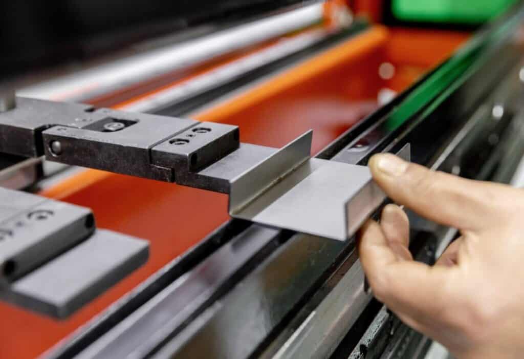
The backgauge determines the flange length of the workpiece.
The X-axis determines the bend line position by controlling the forward and backward movement of the backgauge fingers;
The R-axis determines the positioning of workpieces at different heights by controlling the vertical movement of the backgauge fingers;
The Z-axis assists in stabilizing the positioning of complex parts against the material by controlling the left-right movement of the backgauge fingers.
The accuracy of the backgauge directly determines the dimensional accuracy of the workpiece.
On-site action: Check for finger loosening; Check whether the backgauge operates smoothly; set a fixed dimension and perform repeat positioning tests with the backgauge to verify data stability; regularly inspect the condition of guide rails, lead screws, and connecting components; for complex parts, save the backgauge position parameters in the system for direct retrieval after shift changes.
Key takeaway: The angle of the workpiece is determined by the ram and tooling, while the flange length is determined by the backgauge and workpiece positioning against the backgauge. If the backgauge is unstable, assembly dimensions may deviate.
Control material variables; don’t blame the machine first
Measure actual sheet thickness; don’t rely solely on nominal thickness
Key points:Sheet thickness is the input for bending parameters; the material thickness specified on drawings does not necessarily match the actual measured thickness. Even slight fluctuations in sheet thickness can alter the bending depth, springback, inside bend radius, and flat pattern length.
On-site action: Before each batch of material is processed, first take a random sample to measure the thickness. For large-sized sheets, measure the four corners and the center point, and record the average value. When the measured thickness differs significantly from the nominal thickness, a trial bend must be performed; do not simply reuse the parameters from the previous batch. Finally, the measured sheet thickness data must be recorded on the process card.
Key takeaway: If the sheet thickness data is incorrect, even the most accurate program is meaningless.
Material strength determines springback behavior
Key points: The higher the material’s yield strength, the greater its elastic energy storage, and the more pronounced the springback. Stainless steel, high-strength steel, aluminum sheets, and ordinary carbon steel of the same thickness all exhibit different springback behaviors. Even for materials of the same grade, springback may vary depending on the supplier or batch.
On-site action:
Establish springback compensation records for commonly used materials;
Even if the material grade is the same, materials from different suppliers should not automatically share the same set of compensation values;
Separate parameters must be established for high-strength steel, stainless steel, and aluminum sheets, and they must not be mixed with mild steel;
After switching to a new batch of material, first-piece verification must be performed;
Store the material batch and final compensation values in the program or on the process card.
Key takeaway: The amount of springback compensation required is not determined by experience or intuition, but is derived from the material database and actual springback measurement data from the first part.
Rolling direction affects bending performance
Key points: Steel sheets develop a rolling direction during the rolling process. During bending, the bend line can be “parallel to the rolling direction” or “perpendicular to the rolling direction”; the material’s stress distribution and springback differ in these two scenarios. In particular, high-hardness materials, aluminum alloys, stainless steel, and appearance-critical parts are more susceptible to the influence of the rolling direction.
On-site action: Clearly mark the bending direction on drawings and process cards; When bending high-hardness materials, perform a trial bend first; do not mix different nesting orientations within the same batch of workpieces; for cosmetic parts and high-precision parts, records of their trial bend directions must be retained.
Key takeaway: For the same material and thickness, if the bending directions are inconsistent, batch consistency cannot be guaranteed.
Control the Tooling Before Adjusting the CNC Program
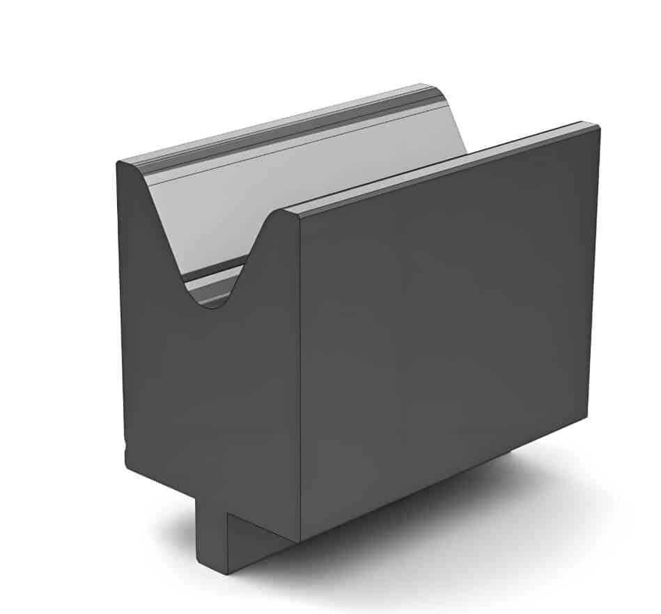
The V-die opening is the core variable in air bending
Key points:
In the air bending process, the width of the V-die opening selection directly determines the size of the inside bend radius, the required tonnage, the minimum flange length, and the risk of surface indentations on the workpiece.
If the V-die opening is too small, the required tonnage will increase sharply, and the risk of surface indentations will also rise;
If the V-die opening is too large, the inside bend radius will typically increase, and short flange lengths may fall directly into the V-die opening.
On-site action:
Do not assume that materials of different thicknesses can share the same V-die opening;
After changing the V-die opening, a trial bend must be performed;
For workpieces with extremely high surface finish requirements, do not focus solely on the angle—also inspect for indentations;
When bending thick plates or long workpieces, calculate the appropriate tonnage and crowning values first;
The final V-die opening size must be recorded in the process card for reference when fulfilling repeat orders.
Key takeaway: In air bending, the V-die opening is not merely a standard tooling dimension; it is a core process parameter that directly influences the bending result.
The punch tip radius must be matched to the material and process
Key points: A sharper punch is not always better. If the punch tip radius is too sharp, it will pierce the material surface like a knife during bending, causing surface indentations and accelerating punch wear. If the punch tip radius is too large, it may fail to meet the forming requirements for some smaller inside bend radii and affect the bending of very short edges.
On-site action:
When selecting tooling, check whether the punch tip radius is suitable for the current material thickness;
When surface indentations on the material suddenly become more severe, immediately inspect the condition of the punch for wear;
Do not use a worn punch for extended periods to bend high-precision parts;
When trial-bending cosmetic parts, simultaneously record the post-bend angle and surface condition.
Key takeaway: If the punch is too sharp, it may damage the material, leading to angle deviation and reduced surface quality.
The influence of upper punch and lower die on bending results
Tooling wear gradually compromises repeatability
Key points:
As the upper punch tip wears down, the actual inside bend radius formed will gradually increase;
As the shoulder of the V-die opening wears down, the actual contact point with the material will change, potentially causing inaccurate bend angles;
If different sections of a multi-section tooling setup experience varying degrees of wear, it may result in localized angle discrepancies in the workpiece.
On-site action:
Clean the tooling surfaces before leaving work each day;
Implement a numbered management system for all tools; Establish a tooling ledger to record the purchase date, usage count, maintenance history, and scrap criteria for each tooling set;
When bending high-precision long workpieces, prioritize segmented tools from the same batch with consistent wear conditions;
Before installing segmented tools, check their height and shoulder condition;
Perform a first-piece verification after every tool change.
Key takeaway:
In most cases, initial tooling wear does not immediately render a workpiece unusable; instead, it causes gradual deterioration in angle repeatability, surface indentations, and localized forming quality. After some time, when the tooling exhibits severe wear, chipping, or angle inconsistency in the segments, it may directly cause localized angle deviations and surface defects.
Therefore, we must implement measures such as regular cleaning and maintaining a logbook to delay tooling wear and ensure workpiece angle repeatability.
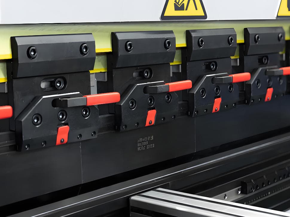
The alignment and clamping determine force symmetry
Key points: If the die centerlines of the upper punch and lower die are not aligned, the ram will experience skewed forces during downward pressure; uneven die clamping may cause angle deviations at both ends of the workpiece; and there may be angle inconsistency due to inconsistent heights in segmented dies.
On-site action:
After each tool change and clamping, check whether the upper die and lower die are aligned and confirm that the clamping system maintains consistent clamping pressure along the entire length;
When using long tools, do not clamp only specific sections;
In the presence of angle inconsistency in the workpiece, prioritize checking the tool clamping status rather than immediately modifying the program;
After clamping a segmented tool, perform a full-length trial bend to verify the results.
Key takeaway: If the tooling is not properly installed, even the best CNC system can only make superficial adjustments and cannot correct deviations caused by force imbalance.
Non-marking bending alters contact conditions
Key points:
When bending surface-sensitive materials such as stainless steel or aluminum sheets, protective films, polyurethane protective pads, nylon die inserts, or non-marking dies are typically used. These protective media alter the contact conditions, friction conditions, and actual force application points between the material and the lower die shoulder.
As the protective media gradually wear down and thin during use, the actual contact conditions change with each bend, causing angle drift.
Therefore, the same program parameter settings cannot be used in both scenarios where protective media are used and where they are not.
On-site action:
Conduct separate trial bends for workpieces using protective media;
Record the type of protective media; replace worn protective media promptly;
Increase the frequency of sampling inspections during batch production of appearance parts;
Simultaneously record the angle data and surface condition of appearance parts.
Key takeaway: Non-marking bending is not simply a matter of placing a layer of film on the lower die. Since the contact state between the workpiece and the tooling has changed, the bending parameters must be readjusted.
CNC parameters must be derived from actual trial bends, not fine-tuned based on intuition
Do not modify bending programs based on intuition
Key points: Parameters such as bend depth, springback compensation, and bending speed are all derived from trial bend results. Operators may use their experience to make emergency adjustments, but this cannot ensure long-term batch consistency.
On-site action:
First, strictly follow standard parameters to perform a first-piece trial bend. Measure the angle only after the workpiece has been fully unloaded and removed from the tooling.
Second, enter the target angle and the measured angle into the system, calculate the difference, and input the angle compensation value.
Finally, perform another trial bend to verify the results. Once verified, save the final parameters to the program. If any modifications are made to the parameters in the program afterward, the reason for the correction must be documented.
Key takeaway: CNC parameters should not merely be adjusted to meet acceptance criteria; they must be transformed into production data that is recordable, reusable, and traceable.
Establish a material database to reduce trial-and-error
Key points: Different materials have varying strengths; applying the same parameters across all materials will result in highly inconsistent bending results. By establishing a material database, we can reduce the number of trial bends required after each material change and accelerate machine setup when processing repeat orders.
On-site action: Save the material grade, thickness, V-die opening size, and tooling combination in the database. When encountering repeat orders, these settings can be directly recalled. When encountering a new batch of the same grade, only minor adjustments to the original parameters are needed for verification, rather than starting from scratch. If abnormal parameters occur, the reason must be clearly documented.
Key takeaway: A truly stable and efficient workshop does not rely on manual experience for repeated trial-and-error adjustments, but rather on the ability to convert successful parameters into standard programs.
Bending speed and dwell time are also consistency parameters
Key points:
If the ram bending speed is too fast, it can generate significant impact forces during the bending process, leading to unstable forming and making springback difficult to predict accurately, which may ultimately result in poor batch consistency;
Dwell time refers to the duration the punch remains at the bottom of the forming stroke; it affects angle stability for thick plates and special materials. For thick sheets (>6 mm), stainless steel, and high-strength steel, trial bends are typically required to determine appropriate bending speed, dwell time, and pressure stability, with the results recorded on the process card.
If the dwell time is insufficient, internal stresses in the material will continue to release after the punch is raised, resulting in greater-than-expected springback and angular deviation.
On-site action:
For high-precision parts, record the ram bending speed and dwell time separately;
After switching materials, do not reuse the bending speed and dwell time from the previous material;
When there is angle variation in the batch, check whether it is caused by speed or dwell time; during batch production, do not arbitrarily change speed parameters;
The final bending speed and dwell time parameters must be recorded in the process card.
Key takeaway: Speed parameters are not merely linked to efficiency; for high-precision bending, bending speed and dwell time are also critical parameters affecting angle consistency.
Crowning is key to consistency in long workpieces
Why do the middle and ends of long workpieces differ?
Key points:
During bending, the ram and worktable typically undergo deformation under load. The longer the workpiece, the thicker the sheet metal, and the higher the material strength, the more pronounced the deflection effect becomes. Insufficient or excessive crowning will cause angle inconsistencies between the middle and ends of long workpieces.
Therefore, on-site operators should not rely solely on visual judgment to determine the compensation direction. Before setting the crowning compensation value, we must first measure the angles at three points on the workpiece—left, center, and right—then determine the direction of angle deviation, and finally decide whether to increase or decrease the compensation value.
On-site action:
First, measure the angles at the left, center, and right points of the long workpiece; do not measure only a single point. Second, if an angle deviation occurs at any position, record it in detail and determine whether the crowning is insufficient or excessive.
Verify the settings again after each change in material, V-die opening, or workpiece length.
Key takeaway: Angle inconsistencies at the center and both ends of a long workpiece are typically not caused by operator error or machine malfunction, but rather by physical deformation of the machine due to stress and issues with crowning. For long workpieces with angle differences between the center and both ends, check the press brake crowning system before changing the bending depth.
Angle inconsistencies between the center and ends of long workpiece
Differences between manual crowning and CNC crowning
Project
Manual crowning
CNC crowning
Adjustment method
Manual setting
The control system calculates or calls up the compensation
Dependencies
Experienced operator’s operating experience
Programs and material parameters
Suitable scenarios
Fixed workpiece type
Multiple materials, thicknesses, and lengths
Changeover efficiency
Slow
Fast
Batch consistency
Depends on operator skill level
Better suited for standardized batch production
Record reuse
Prone to loss
Stored in the program and can be called up at any time
Key takeaway: Manual crowning can only barely address fixed operating conditions, whereas CNC crowning can handle a wider variety of workpieces, multiple lengths, and frequent changeovers.
When is crowning a critical concern?
Key scenarios: When bending long panels, electrical cabinet doors, elevator panels, architectural metal panels, thick structural components, long brackets, workpieces over 3 meters in length, or orders with angle inconsistency at the center and both ends, we must prioritize crowning.
On-site action:
When processing long workpieces, crowning parameters must be recorded separately;
After switching to new materials or V-die openings, the accuracy of crowning values must be re-verified;
During batch production of the same product, the final crowning values must be saved;
And a standard trial bend verification process for long workpieces must be established.
Key takeaway: If the customer places a high priority on the angular stability of long workpieces, the crowning system is the critical equipment for ensuring product compliance.
The X-axis of the backgauge controls the forward and backward position of the backgauge fingers, determining the distance from the workpiece’s positioning edge to the bend line—that is, the flange length / bent flange length.
Finger loosening, worn lead screws or guide rails, sheet metal not flush against the backgauge fingers, or burrs on the sheet edges—these factors can reduce X-axis positioning accuracy, leading to the following issues: inconsistent flange lengths, misaligned hole positions, inconsistent edge distances within the same batch, and significant dimensional errors after multiple bends.
On-site action:
Regularly check that backgauge fingers are securely fastened;
Regularly test the backgauge repeatability;
Operators must ensure the workpiece is firmly against the backgauge fingers each time material is fed;
Check the workpiece edges for burrs;
Reconfirm the positioning reference for multi-bent parts;
And save the backgauge position parameters for repeat orders.
Key takeaway: The bend angle is controlled by the ram and tooling, while the flange length is controlled by the X-axis of the backgauge and the workpiece positioning actions. Only when both the bend angle and flange length are properly controlled can a high-quality workpiece be considered compliant.
The R-axis and Z-axis determine positioning stability for complex parts
Key points:
The R-axis and Z-axis primarily address the positioning of complex parts.
The R-axis controls the vertical movement of the backgauge fingers, enabling precise positioning of complex parts at varying heights;
The Z-axis controls the lateral position of the backgauge fingers, facilitating accurate positioning for irregularly shaped parts, deep-drawn box-type parts, or during multi-station bending operations.
On-site action:
Simulate and plan the material contact points in advance using 3D software;
When performing multi-station bending, save the stop positions; for workshops with frequent changeovers, minimize manual adjustment processes;
If producing a large number of box-type parts, brackets, or electrical cabinet components, prioritize multi-axis backgauge systems.
Key takeaway: The more complex the workpiece, the more valuable a multi-axis backgauge system becomes. It is a key system capable of significantly improving batch consistency.
Operational actions can undermine proper backgauge settings
Key points: No matter how high the precision of the backgauge, dimensional stability can still be compromised by non-standard workpiece positioning against the backgauge, sheet metal not being pressed firmly against the backgauge fingers, inconsistent force applied by the operator when pushing the material, lack of support for large parts, incorrect selection of positioning references after flipping the workpiece, or inconsistent operational procedures following a shift change.
On-site action:
Standardize operators’ workpiece positioning against the backgauge;
Use front support or sheet follower systems for large parts;
For multi-bent parts, ensure the correct flipping sequence and proper positioning reference after each flip;
Operators must re-inspect the dimensions of the first part after a shift change.
Key takeaway: In addition to backgauge precision, correct operating procedures are also a critical factor in ensuring dimensional stability. The workshop must strictly implement standardized management of operators’ working methods.
Press brake backgauge axes for positioning
Bending sequence and workpiece support can amplify errors
Multiple bends can accumulate small errors
Root cause explanation:
In multi-pass bending, each process is interrelated.
For example, if the flange length, angle, or positioning reference of the first pass is off, the second pass will continue processing based on this deviation, and each subsequent pass will continue to accumulate errors.
When U-shaped, Z-shaped, or box-type parts fail to assemble, the issue is often not an error in the final operation, but rather that the positioning reference in earlier operations was already incorrect.
On-site action:
Determine the optimal bending sequence by working backward from the final assembly requirements;
Identify which edges serve as critical reference edges before formal bending;
Verify critical dimensions after each bend; and establish a bending sequence process card for complex parts.
Key takeaway: A multi-step bending process forms a dimensional chain. If the sequence or positioning reference of the first bend is incorrect, all subsequent steps may follow suit.
Bending sequence determines whether the workpiece can rely on the backgauge
Root cause explanation:
An incorrect bending sequence may lead to issues such as unstable backgauge contact or collisions during subsequent processing.
For example, if the large edges are bent first, the small edges may not be able to reach the backgauge during subsequent bends; if deep bends are performed first, the workpiece may collide with the backgauge, tooling, or machine body during subsequent bends.
These issues force operators to temporarily switch backgauge surfaces, manually estimate positions, or alter the workpiece flipping method, thereby reducing batch consistency.
On-site action:
Before starting the bending process, simulate the bending sequence in offline software and evaluate its feasibility;
Check whether deep bends will collide with the backgauge;
For complex parts, use a CNC system equipped with graphical programming or simulation software whenever possible;
During the prototype and sample production phase, document the most stable bending sequence in the process card so that subsequent batch production can follow this sequence.
Key takeaway: No matter how high the machine’s performance, if the bending sequence is incorrect, it is still impossible to fundamentally guarantee bending consistency.
Large parts and thin sheets require stable support
Root cause explanation:
Long, thin sheet metal is prone to sagging due to its own weight, causing discrepancies between the actual and theoretical stop positions, which leads to flange length fluctuations.
During the bending process, the sheet may also warp, lift, or shift as the angle changes. Without a front support, a sheet follower system, or stable manual support, there is a risk of angle inconsistency and flange length fluctuations.
On-site action:
When processing long, thin workpieces with high surface finish requirements or strict dimensional tolerances, prioritize the use of front supports or sheet follower systems.
This prevents sagging due to the workpiece’s own weight, ensures stable support during processing, and maintains accurate angles.
When processing large workpieces, two or more operators must clearly divide tasks and jointly execute standardized operations; for surface-critical parts, additional anti-scratch protection measures should be implemented.
For critical orders, operator movements and workstation layouts should be standardized; and before batch production, actual handling and flipping tests must be conducted.
Key takeaway: The larger the workpiece, the greater the demands on the operator’s movements. If support is inadequate, the machine’s precision may not be fully realized.
Front support device
Build a Closed-Loop Inspection Process, Not Just First-Piece Approval
Verification of the first part only confirms the starting point
On-site action:
First, perform a trial bend according to the program parameters.
After the trial bend is complete, measure the angles of the unloaded finished product (at three points: left, center, and right) and the flange dimensions.
Next, inspect the straightness of the bend line and check the surface for indentations or scratches.
Only proceed to batch production once all inspection items pass.
Finally, record the parameters of the qualified first-piece into the process card.
Key takeaway: A passing first-piece inspection does not guarantee that the entire batch will pass; process inspection is what truly prevents batch scrap.
Simultaneously measure angles, flange lengths, and trends
Test items
Measuring tools
Purpose
Bend angle
Digital angle gauges, angle gauges, online angle measurement systems
Determine angle deviation
Left, center, and right angles
Fixed-point measurement
Verify whether the crowning compensation value is correct
Verify whether the crowning compensation value for long workpieces is set correctly and whether “banana-shaped” deformation occurs
Key takeaway: Relying solely on individual measurement results is not comprehensive enough; it is also necessary to examine data trends. If the data shows even a slight drift, it indicates that a problem is already developing. For a quantified inspection list covering angle, flange length, straightness, and repeatability, refer to our press brake bending accuracy checklist.
Establishing sampling inspection frequencies and re-inspection criteria
Key points: Since precision requirements and batch sizes vary across different parts, their sampling inspection frequencies may not be the same. We need to establish systematic, documented sampling inspection procedures for different parts.
On-site action:
During batch production, conduct sampling inspections at regular intervals;
If abnormal deviations are detected during sampling, increase the frequency of inspections;
If trend-based abnormal deviations occur, immediately halt batch production and first investigate external variables;
Operators must keep records every time they modify a program and must not alter parameters without documentation.
Key takeaway: Without rigorous process documentation following machine setup, it is difficult for the workshop to establish stable production capacity.
Establish process cards and an anomaly review mechanism
The following information should be recorded in process cards:
Category
Records
Material information
Material grade, batch, measured sheet thickness, rolling direction
Tooling information
V-die opening, punch tip radius, tooling number, tooling condition
Program parameters
CNC program number, bending sequence, speed, dwell time
Compensation values
Springback compensation value, crowning compensation value
Key takeaway: If process expertise is not documented in the system, it cannot be retained when personnel, shifts, or materials change, thereby compromising production stability.
If all these checks have been performed but the problem persists, it is not an operator issue.
Issues such as angle deviation in long workpieces, batch-to-batch dimensional drift, difficulty in positioning complex parts, and low changeover efficiency are fundamentally caused by equipment configuration problems.
In such cases, one should reassess and optimize crowning settings, the number of backgauge axes, Y1/Y2 axis synchronization, controller program management, and material support configuration to fundamentally resolve recurring issues.
When the Issue Is Press Brake Configuration, Not Process Control
Just because a standard press brake can produce a sample doesn’t mean it’s suitable for mass production
Key points: If you’re only performing simple 90° bends, a low-spec press brake can handle the job. However, if you need to produce long workpieces, complex enclosures, high-strength steel parts, surface-finished components, or batch orders with frequent changeovers, the requirements for the equipment will be relatively higher.
Key takeaway: The fact that a sample can be bent does not guarantee stability during batch production. When purchasing a press brake, we must prioritize its long-term repeatability.
If these issues recur, the equipment configuration must be evaluated
Recurring issues
Process considerations
Key configuration features
Angle inconsistency at the center and ends of long workpieces
Slow changeover for small-batch, high-variety production
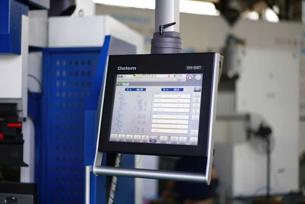
Inadequate program and tooling management
CNC controller, program storage, and graphical programming
Difficulty positioning complex box-shaped parts
Insufficient number of backgauge axes
4-axis/6-axis backgauge
Numerous indentations on stainless steel exterior parts
Poor contact conditions and inadequate pressure control
Appropriate tooling, protection solutions, and stable pressure control
Heavy reliance on operator experience
Inability to standardize process experience
Material database, compensation functions, and automation configuration
Machines must be readjusted for every repeat order
Insufficient program reusability
CNC program management and process database
Which press brake configurations directly support consistent bending?
Configuration
Impact on consistency
CNC crowning system
Reduces angle differences between the center and ends of long workpieces
High-repeatability backgauge
Improves flange length stability
Electro-hydraulic Y1/Y2 servo synchronization
Maintains left-right angle consistency
Multi-axis backgauge
Improves positioning efficiency for complex parts and repeatability in multi-station bending
CNC controller with a material database
Reduces repeated trial-and-error and saves proven parameters with one click
Stable tooling and clamping system
Keeps the tooling aligned and ensures uniform force distribution
Front support / sheet follower system
Improves handling stability for long and large sheets
Optional angle measurement / angle correction system
Reduces manual measurement workload for some high-precision batch parts and helps correct springback-related angle variation
Key takeaway: The purpose of equipment upgrades is to minimize variables caused by human error and ensure more stable machine operation.
On-site checklist for improving bending consistency
Pre-bending inspection
Verify that the material grade matches the drawing specifications;
Measure the sheet thickness;
Verify that the material lot number matches the previous batch;
Observe the rolling direction;
Select the appropriate V-die opening based on sheet thickness and inside bend radius requirements;
Check if the punch tip radius matches;
Check if the upper and lower dies are aligned;
Check if the backgauge operates smoothly and if the backgauge fingers are locked;
Based on the workpiece length, confirm whether crowning is required;
Confirm whether a front support or sheet follower system is needed;
For appearance-critical parts, confirm whether surface protection is required;
Confirm that the CNC program number matches the drawing version.
First-piece debugging
Perform a first-piece trial bend using standard parameters;
After the pressure has fully released and the workpiece has been removed from the tooling, measure the angles at multiple points on the left, center, and right sides of the workpiece;
Use a caliper to measure the flange lengths of each section;
Determine which type of angle deviation the current angles or dimensions represent;
Correct the program parameters or compensation values;
Perform another trial bend using the same production material for verification;
Record the final approved parameters and enter them into the process card.
During batch production
Measure according to the sampling inspection frequency specified in the process documentation;
Use standardized measuring tools;
Measurement positions for workpieces of the same length must be fixed;
After switching to materials from a different batch, first-piece verification must be performed again;
After a tool change, first-piece verification must be performed again;
After an operator shift change, re-inspection must be conducted according to the first-piece standards;
Operators are not permitted to modify program parameters without documentation;
If any trend-based drift is detected, immediately stop the machine and investigate external variables;
For critical orders, retain all process data in full.
After production
Save the final program;
Save the material information associated with this program;
Record the tooling combination used for this batch of products;
Record the V-die opening size used for this batch of products;
Record the springback compensation and crowning compensation values most suitable for this batch of products;
Record the bending speed and dwell parameters;
Record the causes of any abnormalities encountered during this production run and the corrective actions taken;
Save the final inspection data;
Create a standard process card for future repeat orders.
Conclusion
Bending consistency cannot be determined by a single parameter. Material instability can cause angle drift; unstable backgauge can affect flange length accuracy; incorrect tooling selection can alter the contact points between the workpiece and the tooling; incorrect crowning settings can result in angle differences between the center and ends of long workpieces; and non-standard inspection procedures can lead to batch scrap even if the first part passes inspection.
Truly stable bending relies on the coordinated control of materials, tooling, machines, programs, compensation, and inspection processes.
If your workshop frequently experiences issues such as angle drift, flange length drift, angle inconsistency between the middle and ends of long workpieces, low changeover efficiency, or high rework rates, please send us your material type, sheet thickness, maximum bending length, precision requirements, and production volume. Raymax will help you select the appropriate press brake configuration and a bending solution tailored to your specific operating conditions.
Ready To Upgrade Your Metal Fabrication Line?
Email Us For A Free Consultation.
Contact us or request a demo
Fill in the form below and our team will be happy to assist you
Frequently Asked Questions (FAQs)
Improving bending consistency relies on the coordinated control of materials, tooling, machines, programs, and inspection processes. First, measure the sheet thickness and select the appropriate V-die opening and punch tip radius. Second, inspect the tooling wear condition, alignment of the upper and lower dies, and the backgauge repeatability. For long workpieces, enable the crowning system. Finally, record the compensation values through first-piece inspection and in-process sampling inspection, and save them in the program or process card for direct reference when producing repeat parts in the future.
Common causes of inconsistent bending include: fluctuations in material thickness, springback variation, incorrect V-die opening selection, mismatched punch tip radius, tooling wear, unstable backgauge positioning, Y1/Y2 synchronization deviation, incorrect crowning settings, incorrect bending sequence, and insufficient process inspection. When angle or dimensional deviations occur, we must first analyze the type of deviation. For example, if the entire bend line exhibits angle deviation, prioritize checking the material and program; if there is left-right angle deviation, prioritize checking the Y1/Y2 synchronization status and tooling clamping condition; if there is angle deviation in the middle and at both ends, prioritize checking crowning; if angle and dimensional drift occur in batches, prioritize checking the material batch, equipment status, and sampling inspection records.
This is a typical deflection issue in the bending of long workpieces. When bending long workpieces, the ram and worktable undergo a certain degree of deformation under load. If crowning is insufficient or excessive, the angles at the center and ends of the workpiece may differ. When addressing bending issues with long workpieces, measurements should be taken at multiple points—left, center, and right—and crowning, tooling assembly, V-die opening, and workpiece support should be checked.
In most cases, this is not an angle issue, but rather a problem with the backgauge, the way the workpiece is held against the backgauge, or the reference from the previous bend. Backgauge repeatability is poor, backgauge fingers are loosening, the workpiece is not being held flush against the backgauge, there are burrs on the workpiece edges, or the operator applies inconsistent force when pushing the workpiece—all these factors can cause the flange length to drift. For multi-pass bent parts, it is also important to consider whether the positioning of the previous bend affects the next one. Successful assembly of the workpiece depends not only on the angle but also on the flange length.
Yes. CNC crowning can address angle inconsistencies between the center and ends of long workpieces. By compensating for the deflection of the ram and table under load, it ensures more uniform force distribution along the entire bend line, making it particularly suitable for long panels, electrical cabinet doors, elevator panels, and thick structural components. However, its actual effectiveness is also influenced by material properties, V-die opening design, press tonnage, tooling condition, and the method used to measure left, center, and right angles.
Yes. Through Y1/Y2 axis synchronization, multi-axis backgauge, CNC crowning system, material database, angle compensation, and program storage functions, CNC press brakes reduce reliance on manual experience during the bending process, thereby improving consistency for repeat orders and batch production. However, manual oversight is still required for material testing, tooling inspection, and sampling inspection. Only by combining equipment capabilities with process management can truly stable production be achieved.
No. A passing first-piece inspection only indicates that the initial setup is correct; it does not guarantee stable batch production. During batch bending, factors such as material batches, hydraulic oil temperature, tooling wear, operator actions, and program modifications can all cause variations in bending results. For high-precision parts, long workpieces, and appearance-critical parts, it is essential to establish fixed sampling inspection frequencies and measurement points, and to document program modifications, causes of anomalies, and corrective actions in the process card to establish repeatable and stable production capabilities.
In the modern metal bending industry,enterprises face numerous challenges,such as long tooling changeover times,inaccurate positioning,poor repeatability,and human…
When specifying a press brake for tolerance-critical parts, do not start with tonnage and working length alone…
Post Your Review
Share Your Thoughts And Feelings With Others
5 responses to “How to Improve Press Brake Bending Consistency: Causes, Checks & Solutions”
JALE
Hocam Ellerinize Saglık Güzel Makale Olmuş Detaylı
Soap2day
Excellent blog here Also your website loads up very fast What web host are you using Can I get your affiliate link to your host I wish my web site loaded up as quickly as yours lol
Soap2day
Your writing is not only informative but also incredibly inspiring. You have a knack for sparking curiosity and encouraging critical thinking. Thank you for being such a positive influence!
vidsrc
I just could not leave your web site before suggesting that I really enjoyed the standard information a person supply to your visitors Is gonna be again steadily in order to check up on new posts
مكتب تصميم معماري
For the reason that the admin of this site is working, no uncertainty very quickly it will be renowned, due to its quality contents.
We value your privacy
To provide the best experiences, we use technologies like cookies to store and/or access device information. Consenting to these technologies will allow us to process data such as browsing behavior or unique IDs on this site. Not consenting or withdrawing consent, may adversely affect certain features and functions.
Functional
Always active
The technical storage or access is strictly necessary for the legitimate purpose of enabling the use of a specific service explicitly requested by the subscriber or user, or for the sole purpose of carrying out the transmission of a communication over an electronic communications network.
Preferences
The technical storage or access is necessary for the legitimate purpose of storing preferences that are not requested by the subscriber or user.
Statistics
The technical storage or access that is used exclusively for statistical purposes.The technical storage or access that is used exclusively for anonymous statistical purposes. Without a subpoena, voluntary compliance on the part of your Internet Service Provider, or additional records from a third party, information stored or retrieved for this purpose alone cannot usually be used to identify you.
Marketing
The technical storage or access is required to create user profiles to send advertising, or to track the user on a website or across several websites for similar marketing purposes.

-1024x768.jpg)
-1024x768.jpg)
-1024x768.jpg)
-1024x768.jpg)
.jpg)
.jpg)
.jpg)
.jpg)
.jpg)
.jpg)
-1-1024x768.jpg)
5 responses to “How to Improve Press Brake Bending Consistency: Causes, Checks & Solutions”
Hocam Ellerinize Saglık Güzel Makale Olmuş Detaylı
Excellent blog here Also your website loads up very fast What web host are you using Can I get your affiliate link to your host I wish my web site loaded up as quickly as yours lol
Your writing is not only informative but also incredibly inspiring. You have a knack for sparking curiosity and encouraging critical thinking. Thank you for being such a positive influence!
I just could not leave your web site before suggesting that I really enjoyed the standard information a person supply to your visitors Is gonna be again steadily in order to check up on new posts
For the reason that the admin of this site is working, no uncertainty very quickly it will be renowned, due to its quality contents.