
Francis Pan
Francis Pan is the Foreign Trade Manager of RAYMAX, with over 10 years of experience in sheet metal fabrication equipment and CNC machinery. He has worked closely with manufacturers worldwide on press brakes, fiber laser cutting machines, fiber laser welding machines, and practical production-oriented metal processing solutions.
Top Guidelines
-1-1024x768.jpg)
-1024x768.jpg)
-1024x768.jpg)
-1024x768.jpg)
Table Of Contents
Stay in the the loop
Subscribe To Our Newsletter
Quick Answer: What should a press brake FAT/SAT acceptance checklist include?
FAT refers to the factory acceptance test conducted at the manufacturer’s facility before the equipment is shipped;
SAT refers to the site acceptance test conducted after the equipment has been delivered to the customer’s facility and installed and commissioned.
A proper press brake FAT/SAT acceptance checklist should include: test pieces, bending methods, measuring tools, acceptance tolerances, test records, documentation packages, and records of non-conformities.
True acceptance is not determined by whether the first part is bent to the correct angle, but rather by:
Only when the data for multiple consecutive parts is stable does it indicate that the press brake has passed acceptance.
Quick Checklist on the First Screen
|
Acceptance module |
Essential check items |
Risks of not inspecting |
|---|---|---|
|
Machine configuration |
Nominal tonnage, bending length, number of axes, control system, backgauge, crowning system, safety guarding system |
Incorrect configuration, missing optional components, or non-compliance with contract requirements discovered upon arrival at the factory |
|
Test bend |
Angle, flange length, consistency of left, center, and right angles for long workpieces, repeatability for batch production |
The first piece meets angle and dimensional requirements, but there is instability during batch production |
|
Backgauge |
X/R/Z-axis positioning capability, positioning accuracy, backgauge finger parallelism, actual flange dimensions |
Flange length drift, resulting in inconsistent left and right dimensions of the workpiece |
|
Crowning |
Angles of long workpieces (left, center, right), crowning capability, crowning settings, results before and after adjustment |
Angle inconsistency at the center and both ends |
|
Documentation |
FAT report, SAT records, photos, videos, measuring tools, signed documents |
No basis for resolution in the event of future disputes |
|
Contract acceptance criteria |
Angles, dimensions, repeatability, test conditions |
Inability to determine compliance during acceptance inspection |
FAT vs SAT: Two Acceptance Stages, Different Responsibilities
What is a Press Brake FAT?
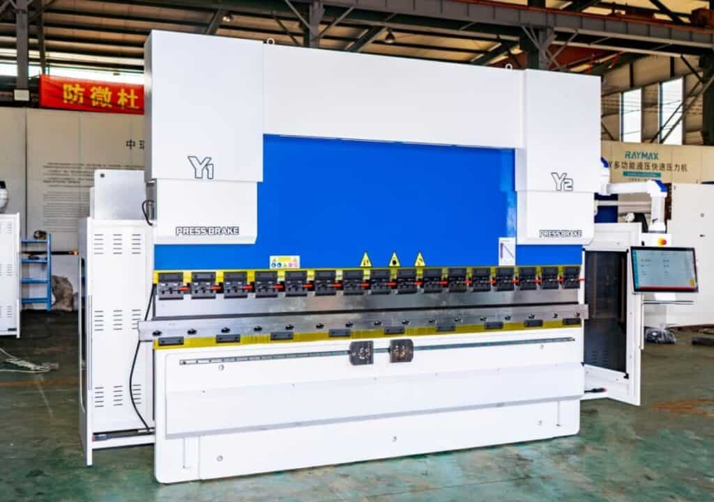
FAT (Factory Acceptance Test) is a factory acceptance inspection conducted at the manufacturer’s facility, prior to shipment of the press brake.
Its primary purpose is to verify that the machine meets the configuration, functionality, accuracy, and documentation requirements specified in the contract.
A valid press brake FAT checklist must confirm the following:
If the customer requires remote video acceptance, the FAT video must also be recorded in accordance with the test procedure. The recording should include the control system interface, tooling installation, test materials, bending process, measurement process, and test records.
.jpg)
What is a Press Brake SAT?
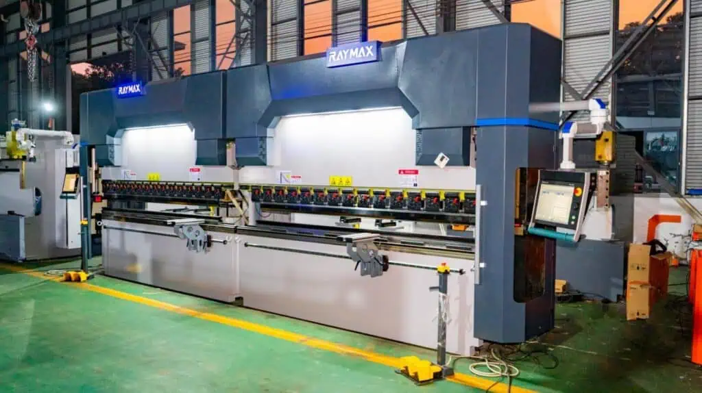
SAT (Site Acceptance Test) is the on-site acceptance inspection conducted after the press brake has been delivered to the customer’s site, and installation and commissioning are complete.
Its primary purpose is to confirm that the press brake’s original condition has not been compromised following transportation, hoisting, installation, electrical connection, and leveling, and that it meets critical acceptance requirements.
SAT does not require repeating all FAT test items, but it must re-test key items that directly impact production readiness. Examples include standard 90° bending accuracy, flange length accuracy, backgauge repeatability, consistency along the full length of long workpieces, and trial bends of typical parts.
.jpg)
Why Might SAT Fail Even After FAT Passes?
This is typically not due to a machine malfunction, but rather to changes in on-site conditions and measurement parameters.
Common causes include: the machine not being leveled, unstable site foundations, power fluctuations, different tooling, different materials, variations in the actual measured sheet thickness, different oil temperatures, different measuring tools, different backgauge positioning methods, and differences in operator technique.
When such issues arise, we must first compare the test conditions of the FAT and SAT item by item, then restore these variables to the same state as the FAT, and finally determine whether the machine actually has a problem.
Checklist Before Testing: 5 Parameters Must Be Fixed First
Test Material and Sheet Thickness
The acceptance record must clearly specify the material grade, actual measured sheet thickness, surface condition of the material, and whether the material used was customer-specified. If necessary, the material’s yield strength or batch number should also be recorded.
Among these, sheet thickness requires particular attention; do not simply record the nominal thickness—the actual measured thickness must be recorded. Even a slight deviation in sheet thickness will directly affect the angle, springback, and flange dimensions.
.jpg)
Bending Length
It must be clearly stated whether the test length is for a short piece or a long piece, as the testing standards differ between the two. For long-piece testing, angle measurements at three points (left, center, and right) must be included, and special attention must be paid to the effectiveness of crowning. Therefore, bending results from short pieces cannot be used to represent those of long pieces.
Tooling Specifications
The following specifications must be clearly documented: punch type, punch tip radius, V-die opening, lower die angle, tool length, and tooling condition. These specifications must match those specified in the contract or test plan.
On the same machine, test results may vary significantly if two different sets of tooling are used. Therefore, tooling specifications must be recorded in the test report to serve as a basis for evaluation during subsequent retests.
Bending Method
It must be clearly stated whether air bending, bottoming, or coining was used.
The default bending method used for FAT/SAT should be based on the method specified in the contract. Since air bending, bottoming, and coining offer different levels of angle control, their acceptance criteria must not be interchanged. For a full comparison of how each method affects angle control and springback, see our guide on air bending vs bottoming vs coining.
.jpg)
Measuring Tools
The acceptance record must also clearly specify the type, accuracy, calibration status, and verification date or calibration validity period of the measuring tools.
Common measuring tools include: digital angle gauges, laser angle measuring devices, vernier calipers, dial indicators, straight edges, and feeler gauges.
For high-precision acceptance, the customer and manufacturer must confirm in advance who will provide the measuring instruments and whether third-party testing is required.
What Acceptance Criteria Should I Write into the Contract?
Mandatory Acceptance Criteria in the Contract
The contract’s acceptance clause must clearly specify at least the following conditions:
These items can serve as the basis for subsequent acceptance decisions. If you are defining angle tolerance, flange length tolerance, crowning requirements, and backgauge repeatability before purchase, this guide on how to spec a press brake for tolerance can help you prepare clearer technical requirements.
Tolerance values must include test conditions
Angle and dimensional tolerances cannot be expressed as a single number; instead, the corresponding material, sheet thickness, bend length, bending method, tooling specifications, and measurement tools must be clearly specified. Otherwise, these numbers will be meaningless.
For example, even for a 90° bend, the bending performance may differ between mild steel and stainless steel, 2 mm and 6 mm sheet thicknesses, 500 mm short pieces and 3200 mm long pieces, air bending and bottoming, and digital angle gauges and laser angle measurement devices, resulting in variations in angle and dimensional tolerances.
We typically include tolerance figures in table examples or contract field examples, annotated as follows:
Do not write acceptance clauses like this
Below is an example of an incorrect way to write acceptance clauses:
From this incorrect example, we cannot derive any useful information. It does not specify which standard is being met, nor does it clearly state the target values, actual values, deviations, or the test materials and procedures.
The correct format should be written as follows:
The FAT report can serve as a milestone for shipment or payment
For procurement projects involving large sums, a signed FAT report can serve as a basis for shipment or final payment. The report must be fully completed, including test data, photos and videos, records of anomalies, and final signatures, to truly hold value for acceptance.
How Do You Test Press Brake Accuracy Before Shipment?
The 5 Core Tests That Must Be Performed During FAT/SAT
When conducting FAT/SAT accuracy tests, these five critical areas must be verified:
Whether the angle is correct, whether the flange length is consistent, whether the backgauge returns to the same position every time, whether the angles at the left, center, and right positions of long workpieces are consistent, and whether the results remain consistent after bending several pieces in succession.
If any of these five items is missing, it is impossible to determine whether the press brake can operate normally in production.
For a broader inspection framework, you can also review our press brake bending accuracy checklist, which covers angle, length, straightness, tooling, backgauge, and machine condition factors.
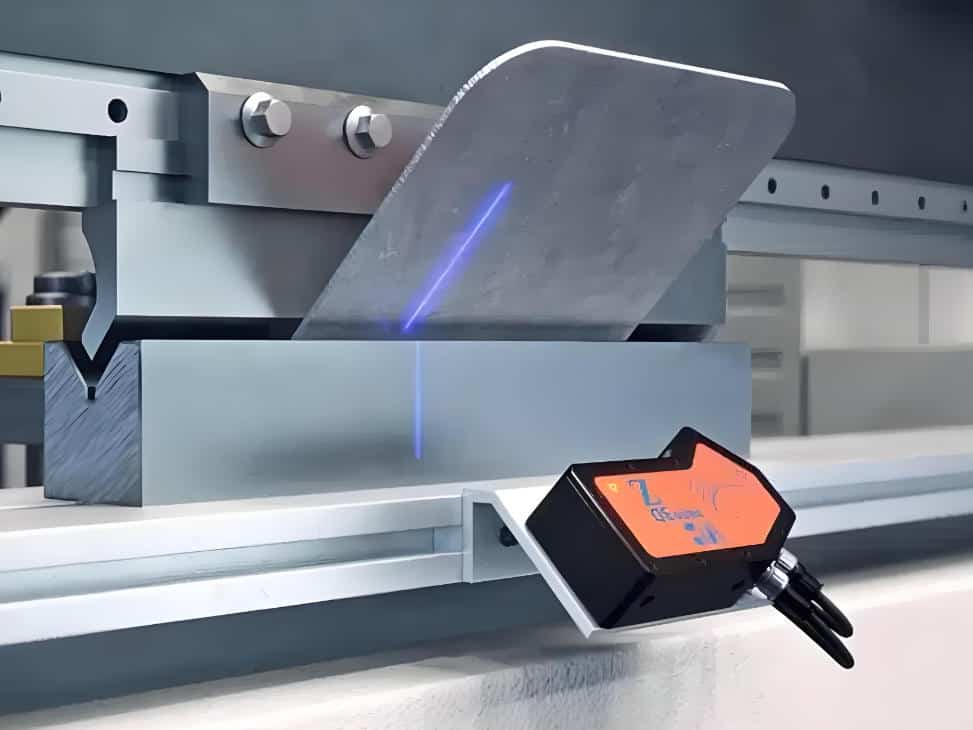
Angle Accuracy Test
If you are unsure how to measure the bending angle correctly, this guide on how to measure press brake bending angle explains common tools, methods, and calibration pitfalls.
Flange Length Verification
.jpg)
Backgauge Repeatability Test
Crowning Verification on Long Workpieces
Multi-piece Bending Repeatability Test
Press Brake Acceptance Test Table
|
Test item |
Test piece description |
Method |
Measurement tool |
Acceptance criteria |
Record format |
|---|---|---|---|---|---|
|
Angle accuracy test |
Material grade, measured plate thickness, bending length |
Air bending, bottoming |
Digital angle gauges, laser angle measuring devices |
As specified in the contract; the target angle, the allowable deviation, and the measurement points must be clearly stated |
Target angle, actual angle, left/center/right angles, deviation value |
|
Flange length verification |
Material grade, measured thickness, target flange length |
Air bending |
Vernier calipers, height gauges |
As specified in the drawings and the contract; the starting point for measurement must be clearly stated |
Target flange length, actual flange length, deviation value |
|
Backgauge repeatability test |
X/R/Z-axis test conditions |
Not applicable |
Dial indicators, gauge blocks, vernier calipers |
As specified in the machine technical documentation or the contract |
Axis name, target position, actual position, maximum deviation value |
|
Crowning verification |
Material, thickness, bending length (≥2000 mm) |
Air bending |
Digital angle gauges, straight edges, feeler gauges |
Refer to the terms specified in the contract; the maximum allowable angle deviation for the intermediate and end angles must be clearly stated |
Crowning setting, left/center/right angles, maximum deviation value |
|
Multi-piece repeatability |
Continuous bending of 5–10 test pieces of the same specifications |
Same program, no parameter adjustments |
Digital angle gauges, vernier calipers |
Refer to the terms specified in the contract; the maximum allowable angle deviation must be clearly stated |
Part number, actual data, range |
|
Safety and function check |
Not applicable |
Not applicable |
Visual and functional testing |
The emergency stop button, foot switch, protective devices, alarm function, and reset function are all operating normally |
Item, Pass/Fail, Remarks |
|
Documentation check |
Not applicable |
Not applicable |
List of documents |
All documentation, including the FAT report, test records, photographs, videos, manuals, and drawings, is complete |
File name, version, what is provided |
How Should You Record FAT/SAT Test Data?
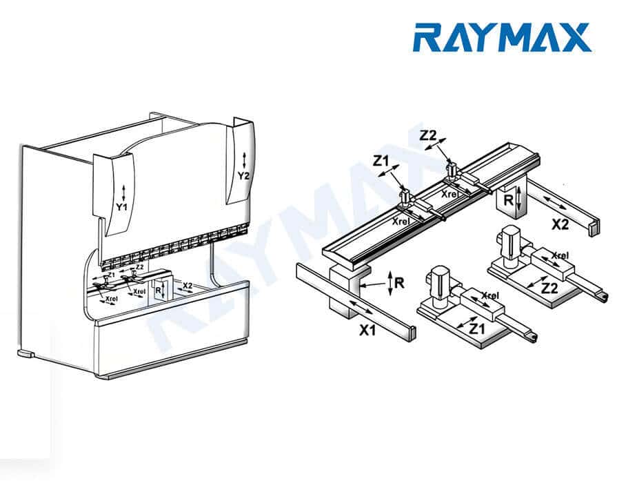
Why Should L-M-R Be Recorded Separately?
For long workpieces, the difference in angles between the center and both ends is a key acceptance criterion. Recording the left, middle, and right angles of the long workpiece separately allows for a direct assessment of whether crowning is effective.
Additionally, any discrepancies in the angles at the left and right ends can indicate issues with Y1/Y2 synchronization, tooling clamping, or the material itself.
Why Should X1/X2 Be Recorded Separately?
When recording flange length, it is not sufficient to note only an average value, as this would mask positioning deviations between the left and right sides.
X1 and X2 must be recorded separately because this allows us to determine whether the backgauge fingers are parallel, whether the workpiece is positioned consistently against the backgauge, whether there are burrs on the workpiece edges, and whether there is a trend of dimensional drift during continuous production.
Why must machine condition be recorded?
On the same press brake, bending results can vary significantly depending on whether the machine is cold or warm, whether it has been leveled, or whether the tooling is properly locked.
Therefore, we must record the following:
Press Brake FAT/SAT Test Record Sheet
|
Part ID |
FAT-001 |
FAT-002 |
SAT-001 |
|---|---|---|---|
|
Material |
Mild steel |
Mild steel |
Customer material |
|
Thickness |
2.0 mm |
2.0 mm |
Measured Sheet Thickness |
|
Bend length |
1000 mm |
2500 mm |
Actual Bending Length |
|
Actual angle L-M-R |
90.2, 90.1, 90.3° |
90.3°, 90.1°, 90.4° |
Record Left, Center, and Right Angles |
|
Target angle |
90° |
90° |
Drawing Values / Contract Values |
|
Target flange length |
50 mm |
50 mm |
Drawing Values |
|
Actual flange X1/X2 |
50.2/50.1 mm |
50.3/50.2 mm |
Record X1/X2 Measured Values |
|
Backgauge axis repeatability |
X: ±0.03 mm |
X: ±0.04 mm |
Record if required |
|
Crowning setting |
0.3 mm |
0.45 mm |
Record crowning setting |
|
Operator |
Operator Name |
Operator’s name |
Operator Name |
|
Date |
Date |
Date |
Date |
|
Machine condition |
Leveled / Preheated / Oil temperature 42°C / Tooling locked / No alarms |
Leveled / Preheated / Oil temperature 43°C / Tooling locked / No alarms |
Installed and leveled / Preheated / Oil temperature recorded / Tooling locked / No alarms |
FAT Documentation and Red Flags in the Report
What Should the FAT Documentation Package Include?
A complete FAT documentation package should include:
Invalid Formulations in the FAT Report
|
Invalid wording |
Correct record |
|---|---|
|
All tests passed |
Record target values and actual values |
|
Good accuracy |
Record deviations and measurement tools |
|
Machine is operating normally |
Record machine status and the testing process |
|
Standard tests completed |
Record materials, thickness, tooling specifications, and bend length |
|
No issues found |
Record non-conformities and the status after retesting |
|
Angle is normal |
Record target angle, actual angle, left/center/right angles, and deviation values |
|
Flange is normal |
Record target flange length, actual flange length, and deviation values |
How should video evidence be recorded?
Do not limit the video to just the machine’s bending motion; instead, include both the bending process and the measurement process.
Specific items to be recorded include:
Video footage can only serve as proof that the machine has undergone testing; it cannot be used as a formal test record. Final acceptance is based on the signed FAT report and test record sheets, which are the only valid documentation.
SAT Recheck: What Must Be Verified After Installation?
Check Installation Conditions Upon Arrival
After the equipment arrives on-site, several basic checks must be completed, including:
Checking the press brake’s surface for transport damage, inspecting the frame, cylinders, and backgauge for damage, verifying that the foundation is level, ensuring the power supply voltage is stable, confirming reliable grounding, checking that the hydraulic oil, lines, and fittings are in good condition, verifying that the backgauge operates smoothly, confirming that the control system can start up normally, and ensuring the machine is properly leveled.
In addition, the safety guarding system requires special attention. Beyond confirming that the exterior is intact, verify that the emergency stop button, foot switch, safety light curtain or laser protection, rear guard, alarm indicators, and reset functions are all operating correctly.
If the machine is not leveled or the foundation is uneven, the subsequent bending result will be unreliable.
Items Requiring Retesting During SAT
The following key items must be retested during the SAT phase:
For standard press brakes, the SAT may use test pieces similar to those used in the FAT for comparison. However, if the application demands high precision, or if the machine will be used for long-term production of cosmetic parts, long workpieces, or batch production, the SAT should additionally include tests using the customer’s actual materials and representative parts.
Check On-Site Variables First When SAT Fails
When SAT measurement results differ from FAT results, do not immediately conclude that the machine is non-compliant. Instead, verify whether the following variables match those from the FAT:
Only after confirming that all of the above variables are correct can it be determined that the machine itself has a problem.
What should the buyer confirm before shipment release or final acceptance?
Before shipment release or final acceptance, the buyer should confirm the following items:
If there are still unresolved issues, they should be included in a list of corrective actions, clearly stating the reasons for correction, retesting methods, and completion deadlines.
If the documents are signed before all issues are resolved, it will be difficult to determine who is responsible if problems arise later.
When Should You Request a Custom FAT/SAT Plan?
When Must You Request a Custom FAT/SAT Plan?
If you require long-term production of long workpieces, high-precision parts, stainless steel components, cosmetic parts, parts with multiple bends, or high-volume production, standard FATs typically cannot meet acceptance requirements, and you must request that the supplier develop a customized acceptance plan.
When encountering the following situations, acceptance testing cannot follow standard procedures; a customized FAT/SAT must be developed based on your actual production conditions:
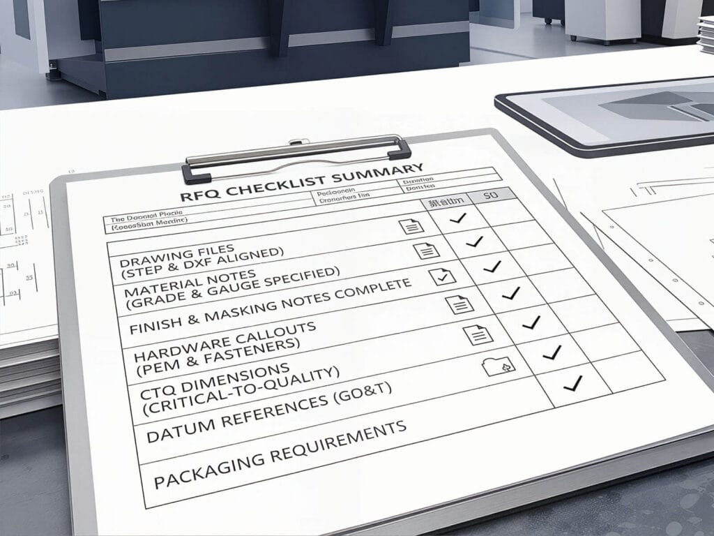
What information should customers provide when making an inquiry?
When making an inquiry, customers should provide the following information:
Only after providing all this information to the supplier can they recommend suitable press brakes, testing plans, and quotations based on your actual operating conditions and requirements. Before sending an inquiry, you can also use this press brake RFQ checklist to organize your material, thickness, bend length, tolerance, tooling, and acceptance requirements.
Ready to Run a FAT on Your Next Press Brake?
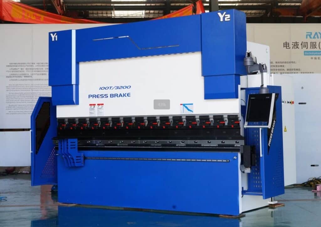
When purchasing a press brake, do not look only at price, tonnage, bending length, and the number of backgauge axes. You should also ask whether the supplier can perform FAT, what test items are included, whether test records can be provided, whether testing can be done with your specific materials and parts, and whether the acceptance criteria can be written into the quotation and contract.
If you are sourcing a CNC press brake, send us your material, thickness, maximum bending length, target angle tolerance, flange length tolerance, and FAT/SAT requirements. Raymax can provide machine selection, acceptance planning, and quotation support based on your production needs. You can also explore RAYMAX CNC press brake lineup to understand available machine configurations.
Ready To Upgrade Your Metal Fabrication Line?
Email Us For A Free Consultation.
Frequently Asked Questions (FAQs)
Related Blog
Pneumatic Press Brake: Complete Guide, Advantages, Applications & Buying Tips
Press Brake Bending Accuracy Checklist: 10 Quantified Factors to Inspect
How to Spec a Press Brake for Tolerance: Angle, Flange Length, Crowning, Backgauge & Acceptance Checklist
Press Brake RFQ Checklist: 14 Fields You Must Provide for an Accurate Quote
What Is a Tandem Press Brake? Benefits, Applications & Buying Tips
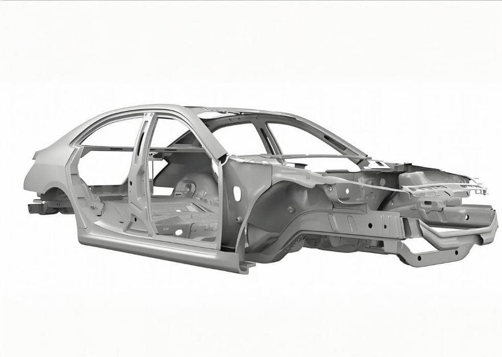
Press Brake for Automotive Sheet Metal Parts: Springback Control, Mark-Free Tooling & Hemming
CNC press brake axis: Mastering Configurations from 2-Axis to 8+1 for Pro Results
NC vs CNC Press Brake: Key Differences, Selection Guide, and Industry Applications

Non-Marking Press Brake Bending: How to Prevent Scratches on Brushed, Mirror-Finish & Film-Protected Sheets
.jpg)
Why Is My Press Brake Angle Inaccurate? Common Causes, Diagnosis Flowchart & Fix Priority
What is a 6 Axis Press Brake? Working Principles, Advantages, Applications, and Buying Guide
Press Brake for Elevator Panels: How to Achieve No-Mark Bending & Perfect Long-Panel Angle Consistency
Post Your Review
Share Your Thoughts And Feelings With Others