
Francis Pan
Francis Pan is the Foreign Trade Manager of RAYMAX, with over 10 years of experience in sheet metal fabrication equipment and CNC machinery. He has worked closely with manufacturers worldwide on press brakes, fiber laser cutting machines, fiber laser welding machines, and practical production-oriented metal processing solutions.
Top Guidelines
-1024x768.jpg)
-1024x768.jpg)
-1024x768.jpg)
-1024x768.jpg)
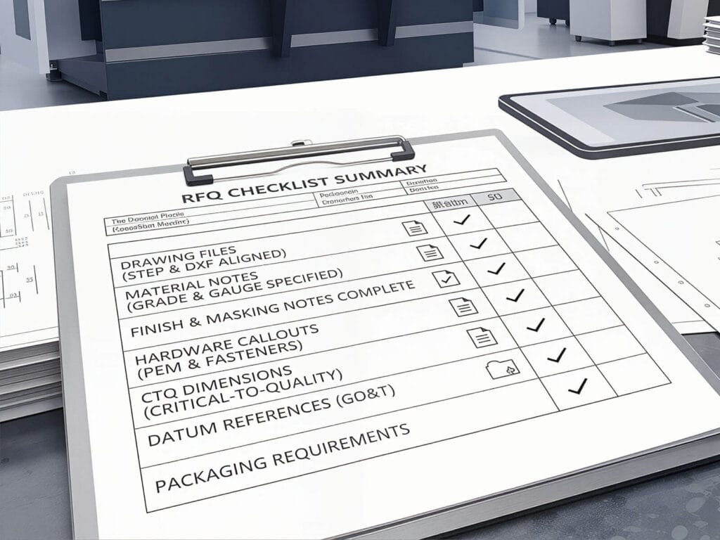
Table Of Contents
Stay in the the loop
Subscribe To Our Newsletter
Summary
When bending angles are off, do not blame machine accuracy or start changing the program blindly. In air bending, angle inaccuracies are usually caused by five factors:
To find the cause of angle deviations, it is important to know what type of angle problem it is: an overall deviation of the entire bend line, a left-right angle difference, a center-to-end angle inconsistency, or a random variation during batch production. If you adjust parameters before identifying the deviation pattern, the problem will only become more confusing. If you identify the deviation pattern correctly, the root cause can usually be narrowed down to five areas: material, tooling, parameters, compensation, or the machine itself. If angle accuracy is a selection issue rather than only a troubleshooting issue, this guide on how to spec a press brake for tolerance explains how to match machine configuration with drawing requirements.
The troubleshooting ideas in this article focus on air bending scenarios. If the current process is bottoming bending or coining bending, the angle formation, springback, and prioritization items will be different and need to be analyzed in a targeted manner, not directly copied.
30-Second Quick Check Table
|
Observed Symptom |
First Suspected Cause |
Initial Check Action |
Fix Priority |
|---|---|---|---|
|
The entire bend line is consistently over-bent or under-bent |
Material springback and program parameters |
Measure the actual material thickness and check the programmed material thickness and V-die opening |
Check input conditions first (actual material thickness + program parameters) |
|
Different angles on each part under the same program |
Process stability |
Check whether the material batch is consistent, whether the tooling clamping is stable, and whether the hydraulic oil temperature is too high |
Check material first, then tooling |
|
Left and right angles are different |
Y1/Y2 synchronization and tooling clamping condition |
Check whether both sides of the ram move down synchronously, whether the tooling is fully seated, and whether the clamping is consistent |
Check tooling first, then the machine |
|
Different angles in the center and at the ends |
Crowning and force distribution |
Check the support condition of long workpieces and whether the crowning value is set properly |
Check compensation first, then the machine |
|
The angle starts to drift after changing the material batch |
Physical properties of the material |
Re-measure the material thickness and do a trial bend to confirm the new springback amount |
Check material first |
|
The first part is correct, but the angle starts to drift during batch production |
System thermal stability or mechanical fatigue |
Check hydraulic oil temperature changes and whether the guideways and connection points have loosened |
Check the machine first, then the process |
Core Diagnostic Tool: Troubleshooting Flowchart for Press Brake Angle Deviation
The standard troubleshooting process is:
Correctly measure the angle of the finished product → determine the type of angle deviation → determine whether it is a first-part problem or batch instability → proceed to machine-level diagnosis.
Start with correct measurement
First, make sure that the angle of the workpiece is measured after the pressure is removed and the workpiece has finished springback, not while the workpiece is under pressure. The reason why many shops adjust their parameters more and more is not because the machine is not capable, but because the timing of the measurement is not right.
Determine whether the deviation is an overall deviation or a distribution-related deviation
Angle deviation should first be divided into two main categories:
It is important to distinguish the type of angle deviation first in order to know which area to look into subsequently.
If it is an overall deviation, check the material first, then the tooling, and finally the parameters
Overall deviation is usually caused by a problem with the input conditions.
The correct troubleshooting process is: first check the actual thickness and strength of the material, then check whether the upper punch and lower die match, and finally check whether the material type, plate thickness, ram stroke depth, and springback compensation settings in the controller match the actual workpiece and process conditions.
Because once the plate thickness, strength, and process parameters are entered incorrectly, the whole bend line will easily produce deviation.
If it is a distribution-related deviation, continue to break it down
Distribution-related deviation is divided into two cases:
When the angle error appears as a stable difference between the center and both ends of a long part, use this press brake crowning troubleshooting guide before changing Y-axis depth or springback parameters.
Determine whether the problem is a first-part problem or instability during batch production
In short, if the first part is off, the input parameters are the likely culprit. If the angle drifts during batch production, suspect system stability.
Only after the above have been checked should you proceed to machine-level diagnosis
When the angle of the workpiece is not correct, do not suspect machine accuracy at first. Instead, give priority to checking factors such as material, tooling, program parameters, and compensation. After these factors have been eliminated, if the problem still exists, then carry out an in-depth machine-level diagnosis — for example, synchronization control, hydraulic system, proportional valve, encoder, or mechanical guideway clearance.
The order of investigation should not be reversed. Jumping straight to machine diagnostics almost always causes you to miss the basic process issues that could have been resolved in minutes.
.jpg)
Diagnose by Symptom: Which Type of Angle Problem Do You Have?
Overall over-bent or overall under-bent
Why is the bend angle still wrong even when the program is set to 90°?
Problems in this category are usually not a result of machine malfunction, but rather a change in the conditions entered into the program.
In air bending, the angle of the final product is not directly determined by the angle of the tooling, but by the combined effect of the ram stroke depth and the springback of the material. If springback is the main reason your angle shifts after unloading, check our guide on how to reduce springback in press brake bending. Once there is a deviation between the actual plate thickness and the program parameters, or there is an error in the springback compensation settings, it may cause the entire bend line to be over-bent or under-bent.
Random angle variation under the same program
If the same program on the same machine, run by the same operator, still produces angle variation from part to part, the issue is process stability rather than simple programming. Common causes include material batch differences, excessive fluctuations in plate thickness, poor repeatability of tooling clamping, and hydraulic oil temperature rise during continuous operation, which slows system response and leads to angle drift.
These factors will continue to affect bending stability, causing the angle to vary from part to part.
Left and right angles are not the same
When the left and right bend angles differ, check Y1/Y2 synchronization first rather than adjusting the backgauge immediately. Because the backgauge mainly affects the positioning dimension, it will not directly determine the angle. Left-right angle difference is usually related to unequal ram stroke depth on the two sides, incomplete tooling seating on the left or right side, or inconsistent tooling clamping on both sides.
Different angles between center and ends
This is the most common problem in the machining of long workpieces. The essence of this phenomenon is the inconsistency of the force along the entire length of the long workpiece. When bending long workpieces, the machine, worktable, and tooling will deform slightly under great pressure, and if there is no proper crowning compensation, the long workpiece may have center-to-end angle inconsistency. For a deeper look at why this happens and how crowning corrects it, read our article on press brake crowning explained.
In addition, improper support, unstable tooling splicing, and sagging of the workpiece due to gravity will further magnify this deviation.
.jpg)
Angle shifts after switching to a new material batch
Many people think that the same material grade means the same springback — this is a typical misunderstanding.
In actual production, even if the material grade is the same, different batches may differ in plate thickness, yield strength, grain direction, and surface condition. Once these conditions change, the springback of the material may also change, and the existing program parameters cannot be applied directly. A trial bend must be done to confirm the actual springback before fine-tuning the program parameters.
On-Site Troubleshooting Priorities — What to Check First, What to Check Later
Follow the troubleshooting sequence in order: first check the basic parameters, then inspect the tooling condition, next verify the compensation settings, and finally inspect the machine itself. If the order is incorrect, troubleshooting efficiency will drop dramatically. For a more systematic inspection sequence, use this press brake bending accuracy checklist.
First priority: check basic parameters
The first step in troubleshooting angle issues is to verify the most fundamental input conditions.
First, use a high-precision caliper to measure the actual plate thickness, then verify that the material type, plate thickness, V-die opening, target angle, and springback compensation in the program match the current workpiece being bent. If the basic operating steps are not clear, first review how to use a press brake for accurate bending, then return to angle troubleshooting and correction.
Only after ensuring the accuracy of these basic input parameters can subsequent corrections be made.
Second priority: inspect the tooling condition
Once the parameters have been confirmed, the next step is to inspect the tooling.
Check whether the upper punch and lower die are fully seated and properly aligned. Inspect the tooling and worktable surfaces for debris, and check the V-die opening and punch tip for visible wear. If the tooling condition is not optimal, the bend angle may become unstable.
.jpg)
Third priority: verify springback and compensation
When neither the material nor the tooling shows obvious issues, verify the springback and compensation settings.
Take a short piece of material from the same batch for a trial bend, measure its actual springback, and then adjust the springback compensation in the program based on the results. For long workpieces, also verify whether the current crowning compensation value is appropriate.
Final step: proceed to machine-level diagnosis
If all the preceding issues have been addressed but the angle remains inaccurate, proceed to machine-level diagnosis.
Key areas to inspect include whether Y1/Y2 axes are synchronized, whether position feedback is functioning normally, whether hydraulic or servo actuator responses are stable, and whether there is excessive play in the guideways and critical connection points.
Troubleshooting must strictly follow the priority sequence. Jumping straight to machine diagnostics almost always causes you to miss the basic process issues that could have been resolved in minutes.
Measure Press Brake Bending Angle Correctly: How to Avoid Compounding Errors
The right time to measure
The angle of the workpiece must be measured after the workpiece is completely out of the tooling and has completed springback. The angle of the workpiece under pressure is not the final finished angle. If the timing of the measurement is not correct, not only will accurate data not be obtained, but subsequent program adjustments may also accumulate error over time.
Correct measuring position
For long workpieces, you cannot just measure at one point. You must measure at the left, center, and right to determine whether the angle deviation is caused by insufficient overall ram stroke depth, or by the center-to-end angle inconsistency caused by machine deflection. If the measurement position changes each time, the recorded data will be meaningless.
Correct measuring tools and measuring procedure
Measuring tools and procedure should be uniform. If different shifts and personnel use different measuring tools and different measuring methods, even the same batch of workpieces may produce different readings. This not only interferes with the operator’s judgment of the angle problem, but also causes the real process issues affecting the angle to be overlooked.
.jpg)
What must be recorded
In addition to recording the final angle, also record the actual measurement location, material batch, plate thickness, the current tooling combination used, the compensation value, and the first-part confirmation result. Only when these conditions are fully recorded does the program become truly reusable for similar jobs.
Beyond Firefighting: Stable Angle Control Requires More Than Manual Adjustment
Why do many workshops always repeat “trial bend — measurement — correction”?
If a workshop is repeating trial bend, measurement, and parameter modification every day, it means that the workshop’s production process has not been truly standardized. Material batch changes are not recorded, tooling combinations are inconsistent, and parameters confirmed for the first part are not written back into the program library. As a result, every production run depends on operator experience, and no reusable process data is ever built. If your goal is not just to fix one bad angle but to improve batch stability, read our guide on how to improve bending consistency.
Which parameters must be standardized and recorded
In order to truly reduce the number of repeated setups and angle deviations, at least the following parameters should be standardized and written back into the program library:
Only by doing so will the program becomes truly reusable for similar jobs when making similar orders in the future.
When the problem is no longer an operational problem but an equipment capability issue
When the shop floor frequently encounters the following situations, the problem is no longer with the operation, but with the limited capability of the machine:
When the above situations occur, it means that the current machine or configuration can no longer meet the machining requirements in terms of synchronization control, compensation capability, and repeatability, and it is difficult to continue completing the current machining tasks in a stable manner.
What configurations really change the results
In machining scenarios involving high-strength steels, long workpieces, high consistency requirements, or frequent changeovers, more advanced Y1/Y2 synchronization, more sensitive crowning compensation systems, more stable clamping systems, and automatic angle measurement capabilities are often needed to truly improve angle accuracy at the root level.
These configurations are the key to upgrading from manual operator experience to system-level control.
Conclusion
A good process engineer can solve occasional angle errors with experience, but if a shop is running “trial bend — measure — correct” every day, it is no longer just a process issue — it is a sign that the current machine or configuration can no longer reliably support your production requirements.
When more and more orders involve high-strength steels, long workpieces, and high consistency demands, you cannot rely solely on manual parameter adjustments. More stable synchronized control, more sophisticated crowning compensation, and more advanced angle control are what truly improve angle accuracy.
If you find your press brake bending accuracy is very unstable, you can send us your drawings and material requirements, and the Raymax engineering team can recommend a suitable press brake machine configuration based on your application.
Ready To Upgrade Your Metal Fabrication Line?
Email Us For A Free Consultation.
Frequently Asked Questions (FAQs)
Related Blog
Proper setup steps for Press brakes and analysis of common calibration issues
The Golden Rule: How to Operate a CNC Press Brake Correctly
What is a Press Brake Operator? Duties, Skills, Salary & Career Prospects Explained!
-1024x768.jpg)
10 Common Press Brake Air Bending Problems: Causes, Troubleshooting, and Fixes
The Heart of Every Press Brake: Select, Maintenance & Upgrade Hydraulic Cylinders
Ultimate Guide to Hydraulic Press Brake Maintenance: Top Tools, Schedules & Expert Tips
Press Brake Tonnage Explained: Learn How to Calculate for Optimal Performance
How to Use a Press Brake Machine for Precise Bending
The Ultimate Guide to Press Brake Safety Devices and Guidelines for 2025
Press Brake Bending Basics: Everything You Need to Know for Efficient Bending
Press Brake Radius Mastery: Inside/Outside Radius, 8× Rule, and Real-World Tips
Hydraulic Press Brake Troubleshooting: The Ultimate Guide to Fix Common Problems
Post Your Review
Share Your Thoughts And Feelings With Others