
Francis Pan
Francis Pan is the Foreign Trade Manager of RAYMAX, with over 10 years of experience in sheet metal fabrication equipment and CNC machinery. He has worked closely with manufacturers worldwide on press brakes, fiber laser cutting machines, fiber laser welding machines, and practical production-oriented metal processing solutions.
Top Guidelines
-1024x768.jpg)
-1024x768.jpg)
-1024x768.jpg)
.jpg)
.jpg)
Table Of Contents
Stay in the the loop
Subscribe To Our Newsletter
Quick answer
The core symptom of a press brake crowning issue is not that the entire bend line is too open or too closed, but rather that consistent angular discrepancies appear at the left, center, and right points along the same bend line. These angular discrepancies typically result from the machine’s deflection under load, as well as a mismatch between the crowning value and actual operating conditions.
When a press brake experiences deflection issues, the most typical symptom is angle inconsistency between the center and the two ends. This is generally categorized into two scenarios:
If the angles at the left, center, and right points are consistently too large or too small, prioritize checking material springback, Y-axis depth, V-die opening, and program parameters; if random fluctuations occur on every workpiece, prioritize checking the material batch, backgauge positioning accuracy, and operator technique.
The correct troubleshooting sequence is: first observe the type of angle deviation, then determine the cause of the deviation, and finally adjust the crowning value.
This article uses the bend angle after the workpiece is removed from the tooling and springback has stabilized as the measurement basis: a larger angle value indicates a more open bend; a smaller angle value indicates a more closed bend.
30-Second Quick Reference Chart: Is This a Crowning Problem?
|
Field symptom |
Initial assessment |
Priority checks |
Do not start with |
|---|---|---|---|
|
The angle in the middle is larger than at both ends |
Insufficient crowning |
Measure the angle at three points—left, center, and right—on the workpiece, and increase the crowning value |
Don’t adjust the Y-axis depth first |
|
The angle in the middle is smaller than at both ends |
Excessive crowning |
Verify that the parameters are set correctly, and reduce the crowning value |
Don’t keep adding compensation |
|
There is a noticeable difference in angles between the left and right ends |
Y1/Y2 synchronization error, uneven tooling clamping |
Y1/Y2 synchronization status, machine leveling, and upper/lower die alignment |
Don’t adjust only the center compensation |
|
The angles on the left, center, and right are all consistently too large or too small |
Material springback, program parameters, V-die opening |
Sheet thickness, springback parameters, and V-die opening |
Don’t set the crowning value first |
|
The angle of each piece varies randomly within the same process |
Material or positioning variations |
Material batch, backgauge positioning, and how the operator pushes the part against the backgauge |
Don’t mistake random fluctuations for a crowning problem |
|
Performance actually worsened after crowning |
Incorrect compensation direction or excessive compensation |
Compensation direction and CNC parameters |
Don’t blindly adjust compensation values |
|
Short pieces are normal, while long pieces are abnormal |
Deflection issues with long workpieces |
Bending length, tonnage, and crowning compensation range |
Don’t apply rules of thumb for short sections |
.jpg)
What Is a Press Brake Crowning Issue — and What Isn’t?
Crowning addresses the angle distribution along the entire length, not the angle at a single point
Crowning compensation essentially compensates for the deflection of the ram, tooling, and table caused by the load on the press brake. It addresses the angle distribution along the entire length, not the angle at a single point.
Many people confuse the Y-axis depth issue with the crowning value:
|
Adjustment target |
What it corrects |
Typical symptoms |
|---|---|---|
|
Y-axis Depth |
The entire bend line is too open or too closed |
The angle deviations at the left, middle, and right points are consistent in direction—either all are too large or all are too small—and the magnitude of the deviations is roughly the same. |
|
Crowning Value |
Angle distribution is inconsistent along the bend length |
A stable angle difference appears between the center and both ends. |
In other words, the Y-axis addresses the issue of “the entire bend being too large or too small,” while crowning addresses the issue of “angle inconsistency between the center and the ends of the workpiece.” For a full explanation of deflection, angle variation, and different crowning system types, see our guide to press brake crowning explained.
Canoe Effect: Why Is There Angle Inconsistency Between the Center and the Ends of the Workpiece?
The “canoe effect” can be understood as the problem of “insufficient penetration in the middle” that occurs when bending long workpieces.
When bending long workpieces, thick plates, or high-strength steel, the machine’s central area experiences significantly greater stress, which causes elastic deformation in the ram, table, and tooling. This deformation does not increase the penetration depth in the middle; instead, it consumes part of the downward stroke, resulting in insufficient actual penetration depth in the central area.
As a result, while the angles at the workpiece’s ends may meet the target specifications, the insufficient bending in the middle section causes the angle there to be greater, making it appear as if the middle has “spread open.”
To resolve this issue, we apply crowning. Simply put, this involves lifting the center of the table in advance before bending, ensuring the middle section achieves sufficient bending depth and maintaining consistent angles along the entire bend line.
Crowning Compensation vs. Springback Compensation
Crowning compensation addresses deformation issues in the machine and tooling system, while springback compensation addresses the elastic recovery of the material after it is removed from the tooling. There is a fundamental difference between the two.
|
Item |
Crowning |
Springback compensation |
|---|---|---|
|
Target for correction |
Deflection of the machine, table, ram, and tooling system under load |
Material elastic recovery |
|
Typical symptoms |
The angles at the center and both ends differ, and there is always a consistent, repeatable angular discrepancy along the length of the workpiece |
Overall angles (left, center, right) are too large or too small |
|
Target for adjustment |
Crowning value |
Y-axis depth, material parameters, springback correction value |
|
Diagnostic methods |
Measurements taken at three points: left, center, and right |
Comparison of overall angles and target angles |
|
Consequences of incorrect adjustment |
The angle across the entire length becomes increasingly inconsistent |
Angle of the first part is repeatedly unstable |
If the angle deviations at the left, center, and right points are similar, check the springback and program parameters first; if there is a significant difference in angles between the center and the two ends, check the crowning compensation settings first. If the issue is springback rather than crowning, see our guide on how to reduce springback in press brake bending.
How to Confirm It’s a Crowning Problem Before Touching Anything
Standard Trial Bend Conditions
Before performing a trial bend, set the following bending conditions:
|
Conditions |
Requirements |
Reasons |
|---|---|---|
|
Materials |
Use the same material batch and record the material grade and strength |
Variations in material batches can interfere with assessments |
|
Sheet thickness |
Measure using a micrometer |
Deviations in sheet thickness can affect angles and tonnage |
|
Bending length |
Use a test piece close to the actual production length |
Short pieces do not reveal true deflection issues |
|
Tooling |
Fixed punch, V-die opening, and clamping method |
Eliminate interference from tooling variables |
|
Process |
Air bending |
Facilitate observation of angle distribution |
|
Target angle |
90° |
Deviation readings are more intuitive |
|
Measurement status |
Measure after the workpiece has completely exited the tooling and springback has stabilized |
Avoid measurement errors |
When measuring angles, use a protractor with calibration, a digital angle gauge, or a measuring tool that complies with factory inspection standards, and ensure that the measurement direction remains consistent at each measurement point.
Three-Point Measurement Method: Left / Center / Right
Procedure: First, perform a trial bend under standard conditions. After the workpiece has completely exited the tooling and springback has stabilized, use a measuring tool to measure the angles at the left, center, and right points, respectively. Record the difference from the target angle, and finally determine the type of problem based on the angle distribution. Before diagnosing crowning, make sure you know how to measure press brake bending angle correctly and keep the measurement direction consistent.
Determination Rules:
|
Measurement results |
Conclusion |
Next step |
|---|---|---|
|
The angle in the middle is larger than those at both ends |
Insufficient crowning |
Increase the crowning value and remeasure |
|
The angle in the middle is smaller than those at both ends |
Excessive crowning |
Decrease the crowning value and remeasure |
|
There is a significant difference in angles between the left and right ends |
Y1/Y2 synchronization, machine leveling, and tooling clamping issues |
Check Y1/Y2 synchronization, machine leveling, and tooling alignment |
|
The angle deviations at the left, middle, and right points are similar |
Springback, Y-axis depth, program parameters, and V-die opening issues |
Check program parameters and material issues |
|
The data for each piece is inconsistent |
Material, positioning, and operator issues |
Check material batch, backgauge positioning, and operational consistency |
Five-Point Measurement Method: Suitable for Long Workpieces and High-Precision Parts
The five-point measurement method primarily involves taking measurements at five specific locations on a long workpiece: the left end, the left quarter, the center, the right quarter, and the right end.
It is typically applicable in the following scenarios:
Using the five-point measurement method helps us more clearly identify variations in angle distribution.
Checklist: Is It Really a Crowning Issue?
Before adjusting the crowning value, make a correct assessment based on the following questions:
If most of the answers are “yes,” it is highly likely a crowning issue; if the answers are inconsistent, you must first investigate issues related to material, tooling, program, and positioning.
What Causes Crowning Issues?
Insufficient Crowning
If the crowning compensation is insufficient, typical on-site symptoms include:
Insufficient crowning indicates that the machine has already undergone deflection under load, but the crowning system does not provide enough upward compensation, so the center angle becomes larger.
Excessive Compensation
If crowning is excessive, typical on-site manifestations include:
When the center angle of a long workpiece is too small, it indicates that the compensation value has exceeded what is required for the current operating conditions. In this case, stop increasing the crowning value and return to a value close to the previous valid setting, then remeasure and fine-tune.
Incorrect CNC Parameter Input
The calculation accuracy of CNC automatic crowning depends on the accuracy of the input parameters. These include:
Material type, measured sheet thickness, bend length, V-die opening, punch tip radius, target angle, and bending method. Additionally, verify whether automatic crowning is enabled and whether manual compensation values have overridden the automatically calculated values.
Even a slight parameter deviation can cause significant crowning errors.
Tooling Misalignment or Uneven Clamping
Common tooling issues include:
When the tooling is not centered, adjusting the crowning merely shifts the error from one location to another and does not resolve the underlying issue.
Mechanical Crowning Mechanism Issues
Issues with the mechanical wedge compensation mechanism—such as wedge jamming, increased lead screw play, motor drive failures, or insufficient lubrication—can also affect crowning results.
When there is a significant discrepancy between the set compensation value and the actual bed displacement, priority should be given to inspecting the wedges, lead screw play, transmission synchronization, and lubrication status.
.jpg)
Hydraulic Crowning Pressure and Response Issues
For hydraulic crowning systems, common failure points include:
For hydraulic crowning systems, it is essential to verify that the hydraulic actuator is actually performing the crowning action; one must not rely solely on the values displayed by the CNC system. For broader hydraulic system failures beyond crowning, refer to our hydraulic press brake troubleshooting guide.
Ram Parallelism and Machine Leveling Issues
If the ram is not parallel or the machine is not level, typical on-site symptoms include:
A noticeable left-right angle difference, which persists even after adjusting the crowning. Additionally, these issues may arise following machine relocation, collisions, or prolonged periods without calibration.
Generally, left-right angle inconsistency is not a typical crowning issue; priority should be given to checking the Y1/Y2 synchronization status, machine leveling, and tooling alignment.
.jpg)
Material and Support Issues Misdiagnosed as Crowning
Many material and support issues are also frequently misdiagnosed as crowning problems. Examples include:
When the bending results vary for each workpiece, priority should be given to controlling the material, positioning, and support rather than directly adjusting the crowning value. If each workpiece shows random variation, check backgauge positioning accuracy troubleshooting before changing crowning values.
Verification method:
Using the same batch of material, have the same operator continuously bend three test pieces using the same positioning method, and record the angles at the left, center, and right positions respectively.
How to Troubleshoot Crowning Issues Step by Step
Step 1: Record the current angle distribution without changing any parameters
Before performing trial bends on thick plates, high-strength steel, or long workpieces, you must first verify the required bending tonnage, tooling load capacity, and machine load limit. If the calculated results exceed the safety limits of the equipment or tooling, you cannot resolve the angle issue by continuing to apply pressure or forcing the crowning adjustment.
After confirming the safety limits, perform trial bends on 3–5 pieces and measure their left, center, and right angles separately. For long workpieces or high-precision parts, use the five-point measurement method directly. Before testing thick plates, high-strength steel, or long workpieces, verify the required press brake tonnage calculation to avoid overloading the machine or tooling.
Step 2: Verify Tooling Condition
Check:
.jpg)
Step 3: Verify CNC Program Parameters
Check whether the parameters entered in the program match the actual operating conditions:
Material type, measured sheet thickness, bend length, V-die opening, punch tip radius, target angle, bending method, crowning mode, automatically calculated compensation values, and manual correction values.
Step 4: Inspect the Mechanical Crowning System
Step 5: Check the Hydraulic Crowning System
Step 6: Fine-Tune Crowning and Retest
After confirming that all the above steps are in order, we can begin adjusting the crowning system’s compensation value. For some mechanical wedge crowning systems, adjustments can be made in increments of 0.02–0.05 mm.
However, the actual adjustment value should be determined based on the machine’s control accuracy, the manufacturer’s commissioning specifications, and current operating conditions.
|
Changes after adjustment |
Note |
|---|---|
|
The central angle has decreased |
Compensation direction is correct |
|
The central angle has shifted from being too large to being too small |
Overcompensation |
|
The central angle remains unchanged |
The compensation mechanism may not have performed the compensation action |
|
The left-right angle difference still exists |
The problem is not with the crowning system |
|
The overall angle of the three points is still too large |
Further adjustment of the Y-axis depth or springback parameters is required |
Step 7: Save Parameter Records
Finally, save all the correct parameters from this run. This includes:
material, measured sheet thickness, bend length, V-die opening, punch tip radius, target angle, original left/center/right angles, adjusted left/center/right angles, final crowning value, operator, date, and whether batch verification was performed.
Only by recording the correct parameters for each operation can a stable, reusable process be established.
Parameter Reference for Crowning Troubleshooting
Parameter Reference Table
The table below serves as a troubleshooting reference based on an air bending process, a target angle of 90°, and ordinary carbon steel (tensile strength ≤500 MPa). Actual results are influenced by machine rigidity, press tonnage utilization, tooling condition, material strength, oil temperature, and measurement methods.
V-die openings for high-strength steel and stainless steel require separate calculation and cannot be directly applied.
|
Thickness range |
Typical V-die opening |
Common trigger lengths for crowning |
Key Diagnostic Points |
Recommended measurement points |
|---|---|---|---|---|
|
1–2 mm |
6–8× sheet thickness |
≥2000 mm |
First, rule out insufficient support for long, thin sheets and material variations |
3 points |
|
3–4 mm |
Around 8× sheet thickness |
≥2000 mm |
Pay attention to the angle difference between the center and the ends |
3–5 points |
|
5–6 mm |
8–10× sheet thickness |
≥1500 mm |
Insufficient compensation is more common |
5 points |
|
8–10 mm |
10–12× sheet thickness |
≥1000–1500 mm |
Simultaneously verify the tonnage, V-die opening, and compensation values |
5 points |
|
≥12 mm |
10–12× sheet thickness or larger |
≥1000 mm |
It is essential to verify the machine tonnage, tooling load capacity, and safety limits |
More than 5 points |
The selection of the V-die opening should be determined based on the material and sheet thickness.
Any change in the V-die opening will also affect the required tonnage, inside radius, springback, and crowning judgment. For a detailed breakdown of V width, material thickness, tonnage, and inside radius, see our V-die opening selection rule.
Reference for Severity of Angle Deviation
The table below serves as a troubleshooting reference for the air bending process, assuming the workpiece has been removed from the tooling and springback has stabilized. Final acceptance is subject to drawing tolerances and customer acceptance criteria.
|
Maximum angle difference between left, center, and right |
On-site assessment |
Action to take |
|---|---|---|
|
≤0.3° |
A minor deviation for most standard structural parts |
Record parameters and continue verification |
|
0.3°–0.8° |
Requires attention; may affect assembly |
Inspect the tooling and materials; minor adjustments may be made |
|
0.8°–1.5° |
Significantly affects overall length consistency |
Troubleshoot according to the crowning procedure |
|
≥1.5° |
Serious anomaly |
Avoid making adjustments blindly; conduct a comprehensive inspection of the machine, tooling, hydraulics, and parallelism |
Whether an angle is acceptable cannot be determined by numbers alone; it must also meet the workpiece acceptance criteria. For welded joints, assemblies, electrical cabinet doors, long profiles, and exterior components, even minor angular deviations can affect final assembly.
Worked Example: Diagnosing Crowning From Angle Data
Input Conditions
Raw Measurement Results
|
Measurement points |
Measured angle |
Deviation from target |
|---|---|---|
|
Left end |
90.4° |
+0.4° |
|
Center |
91.8° |
+1.8° |
|
Right end |
90.5° |
+0.5° |
Diagnostic Process
Example of the Adjustment Process
The following data is provided solely to illustrate the “measure → adjust → remeasure” decision-making logic and cannot be directly applied to other combinations of materials, sheet thicknesses, machines, or tooling.
|
Adjustment steps |
Crowning adjustment value |
left end |
Center |
Right end |
|---|---|---|---|---|
|
Before adjustment |
0mm |
90.4° |
91.8° |
90.5° |
|
1st time |
+0.15 mm |
90.3° |
91.2° |
90.4° |
|
2nd time |
+0.25 mm |
90.3° |
90.7° |
90.4° |
|
3rd time |
+0.32 mm |
90.2° |
90.4° |
90.3° |
From the data above, we can see that after increasing the crowning value, the angle at the center gradually approaches those at both ends, indicating that the crowning is heading in the right direction. After the third adjustment, the difference in angles between the left, center, and right was kept within 0.2°, and the crowning issue has been largely resolved.
Conclusion
In this case, the primary issue stemmed from insufficient crowning. The correct procedure is to first adjust the crowning value to bring the center angle closer to the angles at both ends; if the overall angles at the three points remain too large after adjustment, then adjust the Y-axis depth or springback compensation parameters.
Decision Rules for Crowning Troubleshooting
The key to troubleshooting crowning is to first examine the angle distribution, then decide whether to adjust the compensation, inspect the tooling, check parallelism, or examine the material and program parameters.
Mechanical vs Hydraulic vs CNC Crowning Systems
Strictly speaking, “mechanical crowning” and “hydraulic crowning” primarily refer to the compensation actuators; “CNC dynamic crowning” is more about the control method, typically involving the CNC system calculating compensation based on machining parameters and then driving mechanical or hydraulic compensation mechanisms to execute the correction.
When troubleshooting, we must distinguish whether the control system has calculated incorrectly or whether the actuator itself has failed to operate.
Mechanical Crowning
How it works: Mechanical crowning typically generates the compensation curve using wedges, lead screws, and transmission mechanisms inside the table.
The CNC system or manual adjustment mechanism calculates the required compensation based on the current bending parameters, then drives the wedges to move relative to one another, causing the center of the table to rise upward. This counteracts the deflection deformation of the machine tool caused by the bending load.
|
Item |
Content |
|---|---|
|
Common structures |
Wedge blocks, lead screws, motors, or manual adjustment mechanisms |
|
Main advantages |
Intuitive design, high rigidity, and easy maintenance |
|
Common problems |
Wedge block jamming, lead screw play, insufficient lubrication, and discrepancies in actual displacement |
|
Troubleshooting focus |
Does the set value match the actual bed displacement? |
|
Suitable scenarios |
Long workpieces, medium-to-thick plates, and standard batch production |
Hydraulic Crowning
How it works: The table is equipped with multiple small hydraulic cylinders. During bending, the CNC system applies pressure to the hydraulic cylinders, lifting the center of the table upward to provide compensation; the amount of compensation is directly adjusted by the level of hydraulic pressure.
|
Item |
Content |
|---|---|
|
Common structures |
Table compensation cylinders, hydraulic lines, valve assemblies, control systems |
|
Main advantages |
Fast response, suitable for integration with CNC systems |
|
Common problems |
Hydraulic fluid contamination, unstable pressure, valve assembly lag, compensation cylinder leakage |
|
Troubleshooting focus |
Does the hydraulic system actually respond after the CNC issues a command? |
|
Suitable scenarios |
Multi-specification production, highly automated operating conditions |
CNC Dynamic Crowning / CNC-Controlled Crowning
How it works: Based on the parameters you enter, the CNC system automatically calculates the required compensation and then activates the mechanical or hydraulic compensation mechanism. Some high-end systems can also monitor changes in pressure or angle in real time and automatically adjust the compensation amount.
|
Item |
Content |
|---|---|
|
Working logic |
Calculate compensation based on parameters such as material, sheet thickness, bend length, and V-die opening |
|
Implementation method |
Drive mechanical wedges or hydraulic compensation mechanisms to perform compensation |
|
Main advantages |
Reduce reliance on operator experience and facilitate the creation of a parameter library |
|
Common problems |
Incorrect input parameters, inaccurate parameter library, outdated calibration parameters, or abnormal actuator response |
|
Troubleshooting focus |
Verify the accuracy of system calculations and confirm whether the actuator is actually moving |
|
Suitable scenarios |
Operating conditions involving multiple product varieties, small batches, high-precision parts, and frequent changeovers |
For workshops that frequently bend long parts, the Raymax crowning system helps improve center-to-end angle consistency by matching the compensation method to the actual bending conditions.
.jpg)
Common Mistakes When Troubleshooting Crowning Issues
When crowning adjustments fail repeatedly, the problem is often not the adjustment method itself, but an incorrect diagnosis of the problem type.
|
Common mistakes |
Consequences |
Correct procedure |
|---|---|---|
|
Testing only a single point in the middle |
It is impossible to determine whether the deviation is due to the overall deviation or the distribution |
Measure at three points: left, center, and right |
|
Adjusting the Y-axis depth right from the start |
Although the overall angle has changed, the angle difference between the center and the ends still exists |
First, determine whether the issue is related to crowning distribution |
|
Attributing all angle issues to crowning |
The true issues with materials, tooling, and processes are masked |
Classify by angle deviation type |
|
Failing to record compensation values |
The problem cannot be reproduced after changing operators or operating conditions |
Create a crowning parameter library |
|
Ignoring the V-die opening |
Assessments of tonnage, springback, and compensation may all be incorrect |
Recheck the V-die opening based on material and plate thickness |
|
Testing long parts with short test pieces |
The true deflection problem cannot be identified |
Perform a trial bend using a workpiece close to actual length |
|
Ignoring tooling cleaning and clamping |
Die issues are disguised as failed crowning |
First, check the tooling installation status |
|
Making continuous, drastic adjustments to compensation |
The issue shifts from insufficient crowning to excessive crowning |
Make minor adjustments and verify with measurements |
When Crowning Is Not the Real Problem
The entire bend line is too open or too closed
This is an overall angle issue. You should first check: material springback, Y-axis depth, material thickness, V-die opening, bending method, and program parameters.
Random Variations in Each Workpiece
This is a problem related to material, positioning, and operational stability. Prioritize checking: material batch, sheet thickness variations, backgauge positioning, material feeding action, workpiece support method, and tooling clamping status.
Inconsistency Between Left and Right Ends
This is a problem with ram synchronization, machine leveling, and tooling alignment. Prioritize checking: Y1/Y2 synchronization status, machine leveling, upper and lower die alignment, guide rail wear, and cylinder synchronization status.
How to Prevent Crowning Problems in Production
Establish a Crowning Parameter Library
The parameter library is a key tool for converting trial bend results into reusable processes. After each adjustment of crowning parameters, save the following information to the parameter library:
Material, measured sheet thickness, bend length, V-die opening, punch tip radius, target angle, final crowning value, left/center/right angles, operator, date, and batch verification results.
When encountering similar orders in the future, you can directly retrieve historical parameters for greater efficiency.
Re-validation Required When Operating Conditions Change
Revalidate with a trial bend whenever any of the following conditions change:
Maintenance Schedule
|
Frequency |
Inspection items |
|---|---|
|
Per shift |
Perform a first-piece trial bend, measure the left, center, and right angles, and check the tooling’s cleanliness and clamping condition |
|
Monthly |
Inspect the tooling for wear, check the clamping system, verify the movement of mechanical wedges, and check the hydraulic system for leaks |
|
Every six months |
Check machine leveling and bed condition, and verify the consistency of compensation movements |
|
Annually |
Check Y1/Y2 synchronization, ram parallelism, and the crowning system’s response capability; update the parameter library |
Establishing a regular maintenance schedule is essential for ensuring the stability of batch production.
Crowning System Selection Checklist for New Press Brakes
Under Which Operating Conditions Must Crowning Configuration Be Prioritized?
When the workshop encounters the following operating conditions, the crowning configuration must be thoroughly evaluated:
When processing long workpieces, medium-to-thick plates, high-strength steel, and assemblies, machine deflection, tonnage load, material springback, and angle variations along the full length are all magnified, resulting in a greater need for crowning.
Configuration Considerations for Different Production Scenarios
|
Production scenarios |
Key considerations for crowning configuration |
|---|---|
|
Short parts, thin plates, parts requiring standard precision |
Basic crowning capability, ease of operation |
|
Long workpieces, medium-to-thick plates |
Crowning range, machine rigidity, tooling clamping system |
|
High-strength steel |
Tonnage, V-die opening, tooling load capacity, crowning system |
|
High product variety, frequent changeovers |
CNC-linked compensation and parameter library |
|
High-precision assemblies |
Positioning accuracy, Y1/Y2 synchronization, angular consistency over full length |
The press brake’s tonnage determines whether it can complete the bending operation, while the crowning system ensures angle consistency along the entire length of long workpieces. Both are essential features that cannot be omitted from a press brake.
If your workshop frequently encounters issues with angle inconsistencies between the center and ends of long workpieces, please send us your drawings, material specifications, sheet thickness, maximum bending length, V-die opening requirements, and precision specifications. The Raymax engineering team will develop a suitable crowning configuration, tonnage recommendation, and control system solution based on your specific operating conditions.
Conclusion
Achieving stable bending relies on a system of compensation parameters that can be recorded, reused, and verified.
Troubleshooting deflection issues can be broken down into three main steps:
If your workshop regularly processes long workpieces, medium-to-thick plates, high-strength steel, or assemblies with high angle consistency requirements, you should focus on machine rigidity, crowning system configuration, Y1/Y2 synchronization accuracy, tooling clamping systems, and the control system’s parameter management capabilities.
Raymax can provide appropriate press brake configuration recommendations based on the customer’s specified materials, plate thickness range, maximum bending length, precision requirements, and production type, effectively ensuring angle consistency for long workpieces and reducing the need for repeated trial bends and batch rework. If your workshop frequently encounters crowning issues on long workpieces, explore Raymax press brakes with crowning configuration for more stable long-part bending performance.
Ready To Upgrade Your Metal Fabrication Line?
Email Us For A Free Consultation.
Frequently Asked Questions (FAQs)
Related Blog
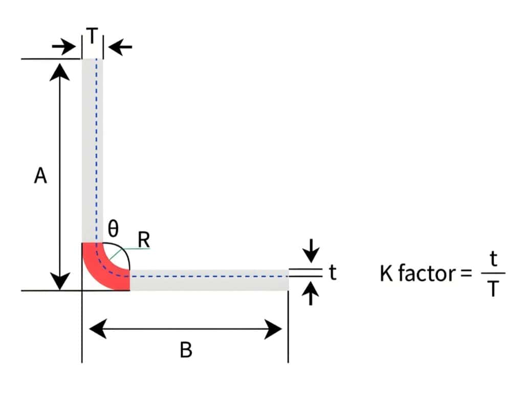
Bend Allowance vs Bend Deduction vs K-Factor: How to Calculate Sheet Metal Flat Patterns (With Examples)
Why Is My Press Brake Angle Inaccurate? Common Causes, Diagnosis Flowchart & Fix Priority
-1024x768.jpg)
10 Common Press Brake Air Bending Problems: Causes, Troubleshooting, and Fixes
What is a 6 Axis Press Brake? Working Principles, Advantages, Applications, and Buying Guide
Press Brake Crowning Explained: Deflection, Angle Variation, Adjustment & System Comparison
How to Choose a Press Brake Control System? Function, Brand & Buying Guide (Including Delem/ESA)

Top 10 Press Brake Manufacturers: How to Choose the Right Supplier
Proper setup steps for Press brakes and analysis of common calibration issues
What is a 4 Axis Press Brake? Configuration, Advantages and Uses analysis
The Ultimate Guide to Press Brake Safety Devices and Guidelines for 2025
An Overview of Electric Press Brake Machines and Purchasing Tips
How to Measure Press Brake Bending Angle: Tools, Methods & Calibration Pitfalls
Post Your Review
Share Your Thoughts And Feelings With Others