


Francis Pan
Francis Pan is the Foreign Trade Manager of RAYMAX, with over 10 years of experience in sheet metal fabrication equipment and CNC machinery. He has worked closely with manufacturers worldwide on press brakes, fiber laser cutting machines, fiber laser welding machines, and practical production-oriented metal processing solutions.
Top Guidelines
-1024x768.jpg)
-1024x768.jpg)
-1024x768.jpg)
-1024x768.jpg)
Table Of Contents
Stay in the the loop
Subscribe To Our Newsletter
Quick Answer
To achieve precise bending, relying solely on an operator’s experience and trial-and-error adjustments is far from sufficient; instead, a consistent verification process for the first-piece must be established. Truly precise bending depends on several key factors:accurate measurement methods, correct program parameters, good tooling condition, and appropriate deflection compensation.
Before commencing batch production, operators must:
This article will guide you through the key operational points for achieving precise bending, teaching you how to ensure more stable bend angles, dimensions, and batch consistency through processes, such as first-piece inspection, measurement of the workpiece, adjustment of parameters, and troubleshooting.
If you place a high priority on bending accuracy and batch consistency, you should not focus solely on tonnage and bending length, when purchasing a press brake. Instead, consider the machine’s CNC system, backgauge configuration, tooling compatibility, and crowning capability. RAYMAX can provide tailored press brake configuration recommendations, based on your workpiece dimensions, material thickness, tolerance requirements, and production capacity.
First-Part Verification SOP
|
Stage |
Items to verify |
Key points for on-site assessment |
What problems can arise if this is ignored? |
|---|---|---|---|
|
Before startup |
Machine level, hydraulic oil temperature, safety devices |
Is the machine operating stably? |
Random drift or safety risks during batch production |
|
Before tooling installation |
Tooling |
Are there signs of wear or metal shavings on the tooling surface? |
Unstable angles, surface indentations, and tooling damage |
|
Material verification |
Actual sheet thickness, material type, material batch, surface condition |
Do not rely solely on the thickness specified in the drawings; actual measurements must be taken. |
Inaccurate assessment of springback, tonnage, and bend depth |
|
Program setup |
Bend angle, bending length, V-die opening, backgauge position, compensation parameters |
Do the program parameters match the actual operating conditions? |
Significant deviations in the first-piece, leading to increasingly chaotic parameter adjustments |
|
First-piece trial bend |
Conduct trial bends using the same material batch as in batch production |
Use the data from the first-piece as a basis for adjustments. |
Significantly increased risk of batch scrap |
|
Angle measurement |
Measure after the workpiece has been removed from the tooling and springback has completed |
Do not attempt to determine the final angle while the part is under pressure. |
Incorrect measurement results and compensation errors |
|
Measurement point selection |
For long workpieces, measure at least three points: left, center, and right |
Determine whether there is an overall deviation or a localized deviation. |
Inability to distinguish between springback, synchronization, or deflection issues |
|
Adjustment sequence |
First check the material, tooling, and measurements; then adjust the program and compensation |
Do not immediately assume the machine is inaccurate. |
Parameters becoming increasingly erratic |
|
Record and retain |
Record the material batch, sheet thickness, tooling combination, program, and actual angle |
Ensure the process is suitable for subsequent batch production. |
Difficulty maintaining stable accuracy after shift changes, material changes, or tool changes |
What should be checked before using a press brake?
Installation and Alignment of the Press Brake
Safety equipment and protection
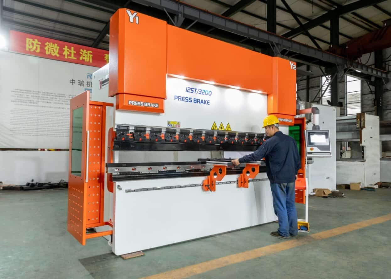
Technical Fundamentals of Precision Press Brake Bending: Tooling, V-Die Opening, Tonnage, and Springback
Selection of press brake tools
1. Key Considerations for Selecting Punches and Tooling
For a complete overview of punch types, die types, tooling compatibility, clamping methods, and setup precautions, read our guide to press brake tooling selection.
2. The Difference Between Air Bending and Bottoming
Calculating Required Tonnage
The calculation of bending tonnage should not rely solely on personal experience, but must comprehensively consider factors, such as material type, measured sheet thickness, bend length, V-die opening, and bending method. The following is a preliminary estimation formula for tonnage, in the air bending process:
F = (C × L × T²) / V
Where:
In conventional air bending, the C value for mild steel can typically be estimated at 650. However, 304 stainless steel has higher material strength and springback, so its C value is also higher; it is typically estimated as 650 × 1.5, which is approximately 975.
If conversion to tonnage is required, the following formula can be used:
Required tonnage ≈ F ÷ 9.81
It should be noted that, this formula is only applicable for preliminary estimates, under conventional air bending processes. In actual production, factors, such as material batch, actual tensile strength, tooling condition, bend angle, minimum inside bend radius, equipment rigidity, and safety margins must also be considered.
For high-strength steel, bottoming, coining, or operations using special tooling, the standard air bending formula, cannot be directly applied; instead, you should refer to the tonnage tables provided by the equipment manufacturer, or use a professional tonnage calculator to recalculate. For detailed formulas, examples, and safety margin recommendations, refer to our press brake tonnage calculation guide.
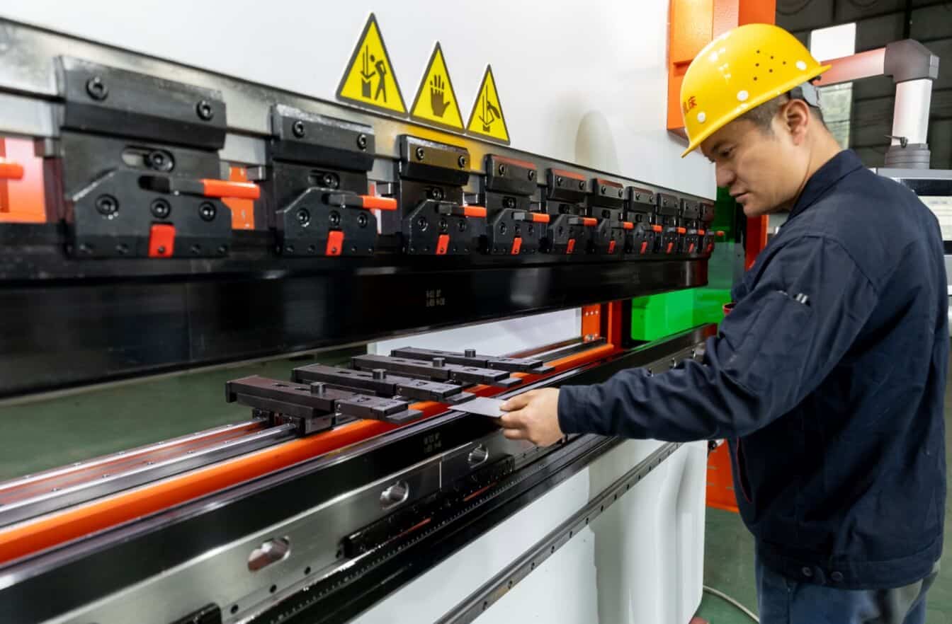
Press Brake Operation: Step-by-Step Setup from Positioning to First-Piece Verification
Material Positioning and Backgauge Setup
Bending angle setting and adjustment
Techniques for Multi-Step Continuous Bending
The key to multi-step continuous bending lies in determining the correct bending sequence in advance, rather than operating cautiously at every step. After completing each bend, the operator should check whether the material reference has shifted, and whether the workpiece might collide with the tooling, backgauge, or machine body.
During the first-piece verification stage, angles and dimensions must be measured at every process step, to confirm there is no cumulative error, before proceeding to batch production.
When Bending Is Inaccurate, Troubleshoot by Deviation Type First
|
On-site symptoms |
Prioritize troubleshooting causes |
Initial troubleshooting steps |
Do not do this first |
|---|---|---|---|
|
The overall angle of the entire bend line is too large or too small |
Material springback, ram penetration depth, measured sheet thickness does not match target |
Verify the material batch, measured sheet thickness, V-die opening, and programmed ram depth |
Do not directly modify all program parameters |
|
There is angle inconsistency at the left and right ends |
Y1/Y2 synchronization accuracy, machine leveling, unstable tooling clamping |
Check machine leveling, ram synchronization, and whether the tooling is securely locked |
Do not judge the part as acceptable after measuring only one point. |
|
The angle in the middle is wider, while the angles at both ends are sharper |
Insufficient crowning |
Measure the angles at the left, center, and right points of the workpiece; check the crowning settings and the force distribution on the worktable |
Do not attribute all problems to material springback. |
|
Flange dimensions are inconsistent |
Backgauge positioning, inconsistent material contact, burrs on workpiece edges |
Check the backgauge position, material contact, and the condition of the workpiece edges |
Do not adjust only the bending angle. |
|
There is angle drift during batch production |
Rising hydraulic oil temperature, variations in material batches, tooling wear, zero-point drift |
Record production time, oil temperature changes, material batch numbers, and trends in angle variations |
Do not adjust the machine based on operator feel. |
|
Errors accumulate after multiple bends |
Bending sequence, backgauge reference, unfolded dimension errors |
Check the bending sequence and changes in positioning references after each bend |
Do not look only at the bend angle of the final bend. |
|
Indentations or scratches appear on the workpiece surface |
V-die opening too small, tooling shoulder wear, insufficient material protection |
Check the V-die opening, tooling surface condition, and protective film |
Do not reduce the pressure first. |
|
Abnormal equipment load or unusual noises |
V-die opening too small, insufficient tonnage, material strength too high |
Stop the machine to recalculate the tonnage and inspect the V-die opening |
Do not continue applying pressure. |
When the center angle differs from both ends on long workpieces, check press brake crowning adjustment before repeatedly changing the bending program.
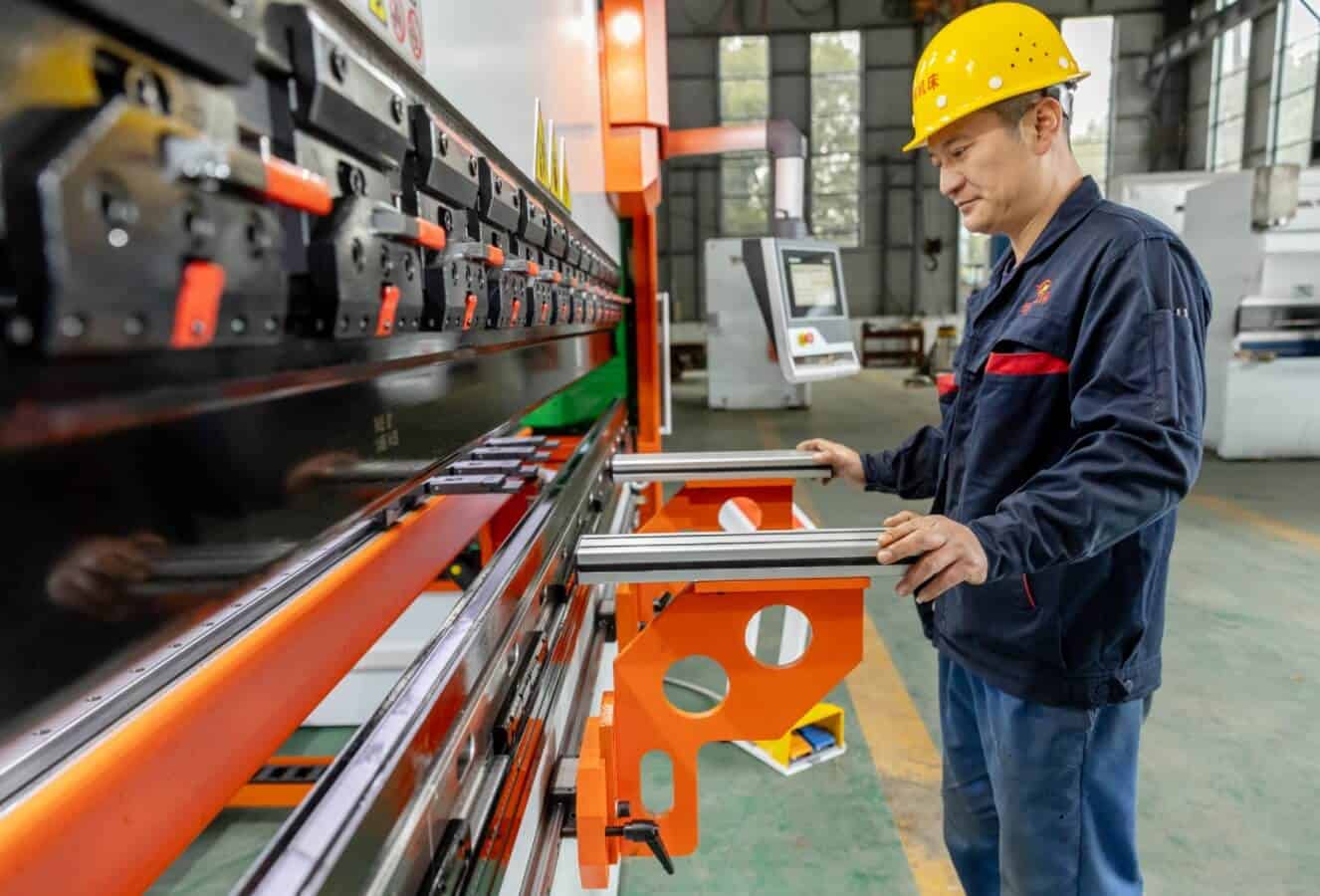
Key Parameter Settings: Lower Die Opening and Springback Compensation
Calculation Method for the V-die Opening of a Press Brake
1. Calculation Method and Formula for the Lower Die Opening
The general formula is W = K × t, where W is the lower die opening width, t is the material thickness, and K is a coefficient, that depends on the material’s yield strength.
2. Relationship Between the V-die Opening, Bending Angle, and Sheet Thickness
How to Perform Springback Compensation on a Press Brake?
1. Definition of Springback
Springback refers to the deviation of the final actual angle from the target angle when the bent material recovers its elasticity.
2. Factors Affecting Springback
The type, thickness, and strength of the material, as well as the angle of the bent part, all influence springback. For the same material, bending along the rolling direction versus perpendicular to it may result in different amounts of springback, and varying risks of cracking. Therefore, during the first-piece inspection, ensure that the material orientation remains consistent with subsequent batch production, and avoid arbitrarily changing the material orientation during batch production.
3. Common Springback Compensation Techniques and Practical Adjustment Methods
Compensation is generally calculated empirically, with the compensation amount determined, based on the material, sheet thickness, V-die opening, and results from the first-piece trial bend. In practice, to ensure precision, factories use CNC parameters to compensate for springback and adjust the settings based on actual results. If angle deviation is mainly caused by material recovery after bending, this guide explains practical methods for springback compensation in press brake bending.
Key Maintenance Points for Stable Bending Accuracy
Daily inspection items
Periodic Inspection and Calibration of Tooling and Angle Measurement Systems
How Does Press Brake Configuration Affect Accuracy Stability?
The press brake’s configuration determines the upper limit of accuracy stability. Different workpiece types, production capacity, and tolerance requirements impose varying demands on press brake configuration. Therefore, when selecting a model, one must not focus solely on tonnage and bending length but also consider the backgauge, ram synchronization, crowning, CNC system, and tooling clamping system.
|
Processing scenarios |
Recommended configurations |
Why choose this option |
|---|---|---|
|
Standard sheet metal parts, symmetrical parts, shallow flanged parts |
3- or 4-axis CNC press brake |
It meets most standard batch bending requirements and makes cost control easier |
|
Long workpieces, wide sheet metal parts, parts requiring high angular consistency |
CNC press brake with crowning system |
It resolves the issue of angle inconsistency at the center and ends of long workpieces |
|
Deep flanged parts, box-shaped parts, asymmetrical parts |
6-axis CNC press brake |
The backgauge offers greater flexibility, reducing the need for manual positioning and trial-and-error adjustments |
|
Multi-step continuous bending, high-frequency changeover production |
Advanced CNC system + multi-axis backgauge |
Batch consistency is determined by excellent program management capabilities, repeatable positioning, and precise positioning references |
|
High-precision batch production |
CNC system + stable tooling system + crowning system |
Bending accuracy is determined by a flexible control system, a crowning system, and a stable tooling system |
If you’re only performing routine sheet metal bending, a basic CNC press brake equipped with tooling and a backgauge, will meet most of your processing needs. However, if you frequently process long workpieces, complex parts, deep-flanged parts, or bent parts requiring multiple bends, or if you have high precision requirements, you should focus on features such as, multi-axis backgauge, crowning capability, ram synchronization, and CNC system capabilities.
RAYMAX can help you determine which configuration best suits your specific operating conditions, based on your workpiece type, material thickness, tolerance requirements, and production capacity needs.
Conclusion
To achieve precise bending, relying solely on experience is far from sufficient; it requires a combination of factors, including: first-piece inspection, accurate measurement, matching of the tooling, program parameters, springback compensation, and equipment configuration. Operators should first establish standardized SOPs. When angle deviations or dimensional deviations occur, they should systematically investigate the causes, based on the specific type of deviation, rather than blindly adjusting equipment parameters, based solely on operator experience.
If your workpieces have high requirements regarding angle, tolerances, batch consistency, or stability when bending long parts, you should not focus solely on tonnage and bending length when purchasing press brake machine. We recommend sending us your workpiece drawings, material thickness, bending length, and tolerance requirements. RAYMAX can provide you with suitable CNC systems, backgauges, crowning, and tooling configuration recommendations.
Ready To Upgrade Your Metal Fabrication Line?
Email Us For A Free Consultation.
Common Questions About Precision Bending with Press Brakes
Related Blog
.jpg)
Why Is My Press Brake Angle Inaccurate? Common Causes, Diagnosis Flowchart & Fix Priority
-1024x768.jpg)
How to Measure Press Brake Bending Angle: Tools, Methods & Calibration Pitfalls
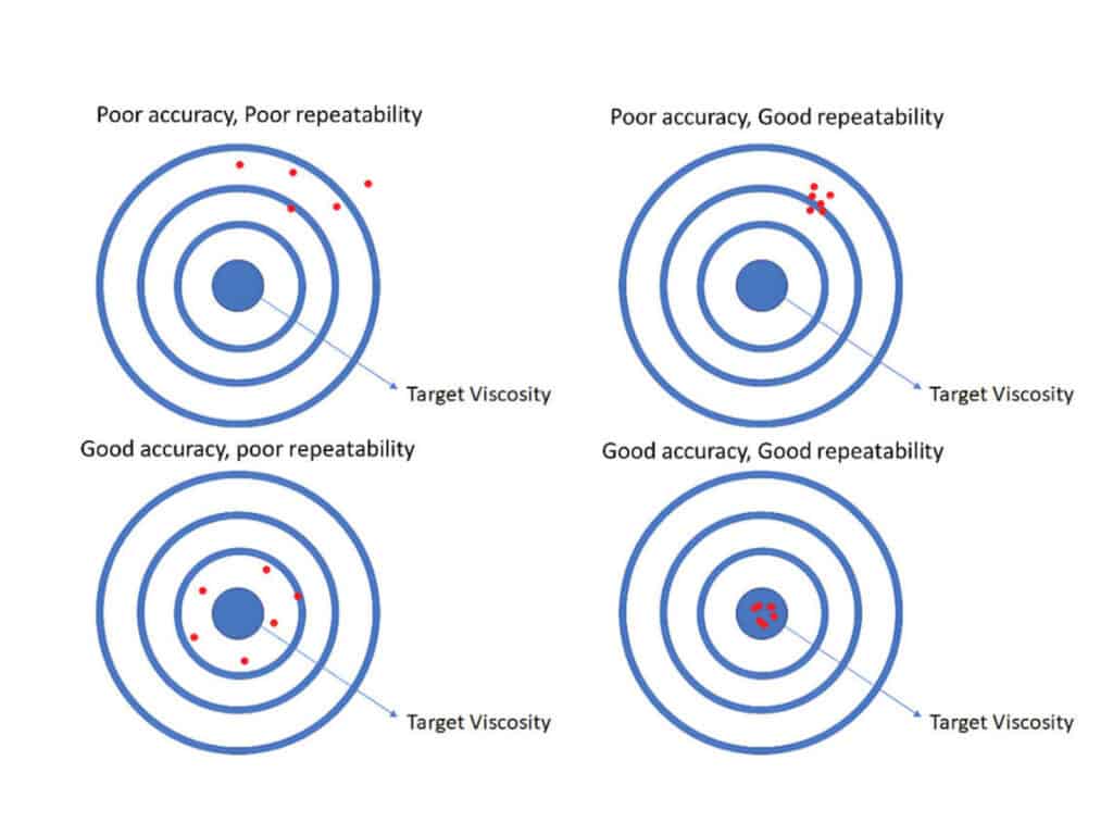
Press Brake Repeatability vs Accuracy: Definitions, Test Methods & Common Misunderstandings

Press Brake Clamping System Guide:Types,Tooling Compatibility&Faster Tool Changeovers
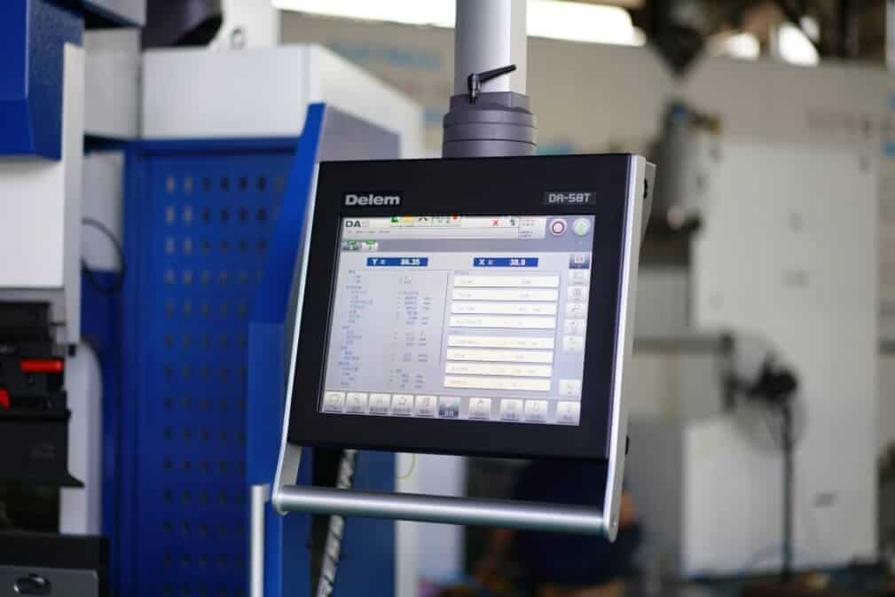
Proper setup steps for Press brakes and analysis of common calibration issues
-1-1024x768.jpg)
How to Spec a Press Brake for Tolerance: Angle, Flange Length, Crowning, Backgauge & Acceptance Checklist
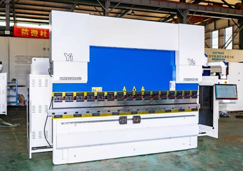
Press Brake Radius Mastery: Inside/Outside Radius, 8× Rule, and Real-World Tips
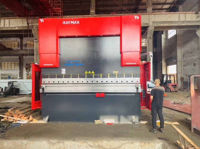
The Golden Rule: How to Operate a CNC Press Brake Correctly
-1024x768.jpg)
Press Brake Crowning Troubleshooting: Fix Uneven Bend Angles Across Long Parts
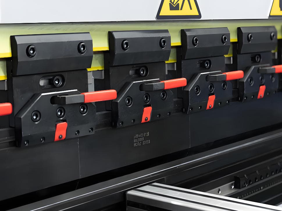
Press Brake Quick Clamping System: Types, Compatibility & How to Choose (Quick Clamp Guide)
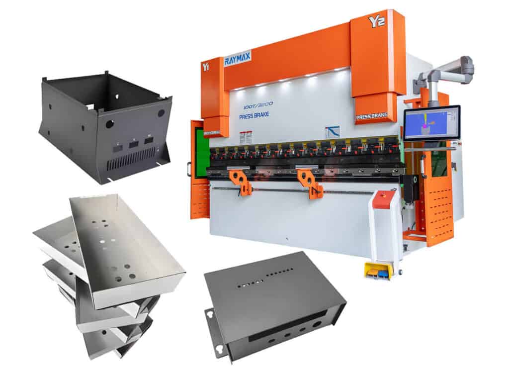
Electrical Enclosure Bending: Flat Pattern, Flange Accuracy & Fit-Up Issues
What Is a Press Brake Used For? 16 Industry Applications and 8 Types of Bends
Post Your Review
Share Your Thoughts And Feelings With Others