


Francis Pan
Francis Pan is the Foreign Trade Manager of RAYMAX, with over 10 years of experience in sheet metal fabrication equipment and CNC machinery. He has worked closely with manufacturers worldwide on press brakes, fiber laser cutting machines, fiber laser welding machines, and practical production-oriented metal processing solutions.
Top Guidelines
-1024x768.jpg)
-1024x768.jpg)
-1024x768.jpg)
-1-1024x768.jpg)
Table Of Contents
Stay in the the loop
Subscribe To Our Newsletter
Introduction: Four Key Criteria for Press Brake Tooling Compatibility
To determine whether a set of press brake tooling is compatible, simply check these four conditions: clamping standards, working height, tooling centerline, and tooling load capacity. If any one of these conditions does not match, the tooling set is not truly compatible; it has only been force-fitted.
If any one of the above four items fails to meet the requirements, batch production cannot proceed.
If a tooling set requires repeated adjustments just to be barely usable, it indicates that it is not truly compatible. A truly compatible press brake tooling system should be capable of stable positioning, repeatable clamping, alignment between the punch tip and the lower die V-opening center, and should not shift unpredictably under its rated load capacity.
What Determines Press Brake Tooling Compatibility?
Tooling compatibility cannot be determined by visual inspection alone. Clamping methods, working height, centerlines, load capacity, die holder matching, and segmented tooling—if even one of these criteria fails to meet standards, the tooling set cannot be considered truly compatible.
Compatibility Is Not Just “Fitting In”
Many people believe that if a die fits into the clamp, it is compatible; however, this assessment is far too simplistic. The fact that a die fits into the clamp merely indicates that there is no dimensional conflict between the die and the clamp; it does not guarantee that the clamping reference, load-bearing reference, and tooling centerline are necessarily aligned.
To achieve true compatibility, seven conditions must be met:
The greatest danger on the shop floor is not that the die cannot be installed, but rather that it can be installed under no-load conditions yet begins to shift when the machine is actually performing the bending operation. This situation can very easily lead to inaccurate angles, indentations, and die damage. In addition, once punch and die compatibility is confirmed, high-mix shops should also evaluate tooling and clamping ROI for high-mix production before choosing manual, quick, or hydraulic clamping.
Tooling Compatibility Is an Issue for the Entire System
Tooling compatibility is not merely an issue with a single upper punch or lower die, but rather an issue for the entire tooling system. From top to bottom, this includes: the ram / upper beam, upper clamp, punch holder, punch tang, punch tip, lower die, die holder, crowning system, lower table, adapter, and segmented tooling. If any component in this system is misaligned, the bending result will be off.
What Does This Article Cover?
This article does not explain every tooling type in detail. For a broader overview of punch profiles, die forms, V-openings, gooseneck tools, and basic selection rules, start with our press brake tooling guide. This article focuses on whether a tooling set can be mounted, centered, loaded safely, and used for stable production.
This article will focus solely on analyzing how to determine whether a die set is compatible, including:
In other words, the focus of this article is on determining whether a tooling system can support stable production.
Press Brake Punch and Die Standards: European, American, WILA / Trumpf
European-style, American-style, and WILA New Standard / Trumpf-style tooling are three distinct tooling systems. The core differences between them lie in punch tang width, safety structure, bearing shoulders, holder interfaces, and centerlines; these three systems are not interchangeable.
Table of Core Parameters for the Three Standards
|
Tooling system |
European / Promecam / Amada-style |
American-style |
WILA New Standard / Trumpf-style tooling |
|---|---|---|---|
|
Upper punch tang reference dimensions |
13mm |
12.7mm |
20mm |
|
Safety structure |
Safety groove on the operating side; load is transmitted via the bearing shoulder |
Relies heavily on mechanical clamping plates and straight-tang or safety-tang structures |
safety click / locking button / system-specific lock |
|
Die base width |
Commonly available in 14 mm or 60 mm |
Compatible with the American holder system |
Compatible with dedicated lower holder or crowning table |
|
Typical applications |
Modern CNC press brakes, segmented tooling, quick-clamping system, and frequent tool changes |
Traditional press brakes, full-length dies, infrequent tool changes, long straight edges |
High-precision bending, requiring quick tool changes, multi-station, and automated bending |
The 13 mm, 12.7 mm, and 20 mm values in the table are the reference dimensions for the punch tang widths of the three types of tooling systems. This dimension is critical and must be clearly specified. However, even within the same system, different brands may have variations in their safety groove, shoulder height, locking slot, tool height, and holder precision grade; therefore, the specifications indicated on the manufacturer’s drawings should always be used as the final reference.
The 0.3mm Trap: 12.7mm Is Not 13mm
The American-style tooling punch tang width of 12.7mm and the European-style tooling punch tang width of 13mm differ by only 0.3mm, making it difficult to distinguish them with the naked eye. However, when matching clamping systems, this 0.3 mm is by no means a minor error; it alters the contact point between the punch tang and the clamp, the load-bearing surface of the bearing shoulder, the locking status of the safety groove, and the centerline of the load.
Therefore, under no circumstances should different systems be mixed by force-fitting, using shims, or grinding the tang.
How to Distinguish the Three Major Systems
European / Promecam / Amada-style tooling
The most distinctive feature is the 13 mm upper punch tang. Modern CNC press brakes, segmented tooling, and quick-clamping systems often use this tooling standard. Its lower die base is typically 14 mm or 60 mm and must be matched to the die holder.
American-style tooling
The most distinctive feature is the 12.7mm punch tang. This tooling standard is commonly used in traditional press brakes, the North American market, and applications requiring full-length dies. Most American-style dies feature a one-piece construction, offering high rigidity and lower cost per meter when bending long straight edges. They are particularly well-suited for long straight-edge parts and production scenarios with infrequent tool changes.
WILA new standard / Trumpf-style tooling
The most distinctive feature is the 20mm punch tang. It enables automatic positioning, rapid tool change, and high clamping repeatability. Its value lies in the ability to coordinate the die base, clamping system, crowning system, and die parameters to achieve high-precision, automated bending.
.jpg)
Adapters Can Be Used Across Systems, but at a Cost
Adapters enable mechanical conversion between different die standards, but they also increase the total height of the die once clamped, which means they occupy a portion of the open height (typically 50–100 mm, depending on the adapter’s structure and the holder’s height). Furthermore, any additional connection interface reduces the die’s rigidity and increases alignment errors.
When bending deep box parts, enclosures, thick plates, and high-precision batch parts, the requirements for open height, centerline alignment, and die rigidity are inherently higher; therefore, adapters should be used with caution. Furthermore, adapters must be sourced from the machine tool manufacturer or a professional die supplier—do not improvise by piecing together materials on-site.
Punch Holder / Die Holder / Clamping Fit Table
When clamping the die on a press brake, it is essential to ensure that the upper punch tang, clamping method, lower die holder, and V-opening centerline are all properly aligned. Any misalignment at any interface will cause angle deviation or die damage under the bending force. Before checking punch and die fit, you should first understand how different press brake clamping systems lock, support, and position the upper tooling.
Core Reference Table
|
Clamping systems |
Key considerations for upper punch matching |
Key considerations for lower die matching |
Suitable applications |
Situations not suitable for |
Shop-floor risks |
|---|---|---|---|---|---|
|
Manual clamping plates |
Punch tang width, clamping plate contact surface, locking bolts, bearing shoulder |
Standard die holder, 4V-type lower die, single V die |
Full-length dies, traditional American-style tooling |
Tooling requiring frequent tool changes or high-precision segmented tooling |
Uneven pressure, difficult to adjust |
|
Standard quick-clamp |
Safety grooves, front-loading method, clamping block structure, locking direction |
Standard die holder |
European-style segmented tooling |
Old tooling without safety grooves or with mismatched upper punch tangs |
Tooling not clamped securely, centerline misalignment |
|
Hydraulic upper clamp |
Punch tang, safety structure, reference surface alignment, self-aligning structure |
Precision die holder or crowning table |
High-precision segmented tooling, multi-station bending, frequent tool changes |
Standard tooling without matching safety grooves |
Slippage under load, damage to clamps |
|
Pneumatic upper clamp |
Tool weight, tool change frequency, locking structure |
Standard die holder |
Light- to medium-duty segmented tooling |
Heavy-duty thick-plate tooling and extra-long tooling |
Insufficient clamping force or low efficiency |
|
WILA / Trumpf |
20 mm punch tang, dual-side safety grooves, system lock, safety click |
Corresponding die holder or crowning system |
High-precision quick-change systems, segmented tooling, multi-station bending |
Mixed tooling from different systems |
Unable to install or loss of system advantages |
|
Adapter solutions |
Adapter interfaces at both ends, total height |
Limited by the original machine’s die holder |
Upgrading older machines, transition period for old tooling |
Machines with limited open height or deep box-shaped parts |
Insufficient effective open height, large cumulative error |
Five Points to Check for Upper Punch Fit
To determine whether the upper punch fits, check the following items:
For a deeper explanation of punch profiles, punch tangs, shoulders, and tool materials, see our guide to press brake punches. The bearing shoulder is particularly critical, as it is primarily responsible for transferring the bending forces from the die to the clamping system; therefore, it must be in full contact with the clamping reference surface. Furthermore, when using older dies without safety grooves, the quick-clamping system cannot be fully locked in place. This not only affects tool change efficiency but also poses serious clamping risks.
Five Points to Check for Lower Die Fit
To determine whether the lower die fits properly, check the following items:
Lower die compatibility is not only about whether the die can sit in the holder. To understand die types, V-openings, and die selection rules, read our guide to press brake dies. When assessing lower die compatibility, the die V-opening centerline is actually the most commonly overlooked factor. Many people focus only on whether the upper punch is securely clamped, but forget that even a slight misalignment of the die V-opening centerline will cause the entire bend line to shift. Just because the lower die fits into the die holder does not mean the die V-opening centerline is necessarily aligned correctly.
Therefore, when installing used dies, reground dies, non-standard dies, or multi-V dies, the positioning reference must be re-verified.
.jpg)
The Height / Shut Height Must Be Entered into the CNC
For CNC press brakes, die parameters are critical. Therefore, we must ensure the following:
Press Brake Tooling Compatibility Checklist
If any one of the 8 items in the Press Brake Tooling Compatibility Checklist does not comply, orders cannot be placed or batch production initiated.
Printable 8-Item Checkbox Checklist
Clamping standard
Is the clamping system European / Promecam, American, WILA / Trumpf, or an OEM-specific system? (Check the manual and clamping drawings; do not rely solely on visual inspection.)
Punch tang / slot
Is the punch tang 13 mm, 12.7 mm, or 20 mm? Do the safety groove, locking slot, and shoulder height match the clamping system?
Upper clamp type
Is the current clamping system manual, quick-clamp, hydraulic, or pneumatic? Is it compatible with the safety structure of the current upper punch?
Die holder / lower holder
Do the die base width, locating slots, V-opening centerline, and die height match the die holder, lower holder, or crowning table?
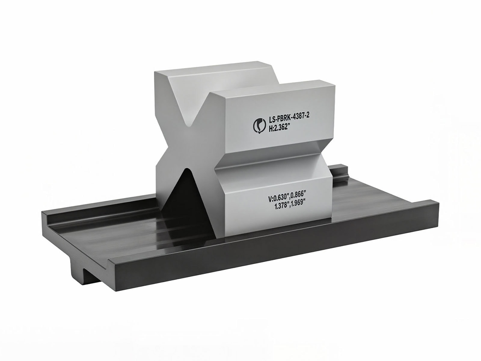
Working height / daylight
Does the total height—comprising the upper punch height, lower die height, adapter height, formed workpiece height, and part removal clearance—fall within the permissible range of the effective open height?
Centerline
After downward pressure is applied, is the punch tip exactly centered in the V-opening center? Is contact uniform front to back?
Tooling load capacity
The die’s rated capacity in tons/m or kN/m must account for the material, sheet thickness, V-die opening, bend length, and bending process. When processing thick sheets, long workpieces, high-strength steel, or stainless steel—or when using a small V-die opening for air bending, bottoming, or near-bottoming, a safety margin must be allowed.
The tooling’s rated load capacity in tons/m or kN/m is not the same as the machine’s rated tonnage. Do not assume that because a machine is labeled “160T,” the die can withstand 160T of bending force; you must convert the value based on the actual bend length.
The rated tooling load capacity is typically specified in tons/m or kN/m. When determining whether a die can handle a bend, first calculate the actual bending force based on material strength, sheet thickness, V-die opening, bend length, and bending method. Then verify that the punch, die, clamping system, and lower die holder can all withstand this force. Do not assume that just because the machine’s tonnage is sufficient, the die will necessarily withstand the force—these are two separate matters.
Segmented tooling fit
Are the height, length combinations, assembly sequence, positions of the left and right ends, and clearance spaces consistent for segmented tooling? Have new and old segmented tooling sets been mixed together during assembly?
Working Height / Daylight Assessment
The actual working height of a press brake cannot be determined solely by the machine’s open height; rather, it must be calculated as the total height resulting from the sum of the upper punch height, die height, adapter height, the height of the formed workpiece, and the part-removal clearance.
When producing enclosures, deep boxes, or parts with large flanges, additional space must be reserved for flipping and part removal.
Furthermore, the adapter occupies effective height; the specific amount of space occupied depends on the adapter’s structure and the holder’s height.
V-die opening and sheet thickness
The size of the V-die opening affects tonnage, inside radius, springback, indentation, and tooling load capacity; therefore, the selected V-die opening must be matched to the material and process. In air bending, the common reference range for the V-die opening is 6–12 times the sheet thickness.
Mild steel, stainless steel, aluminum sheets, and high-strength steel cannot be treated with the same reference value; the decision must be based on material strength, sheet thickness, target inside radius, process method, and tooling load capacity.
Detailed V-die opening selection should be handled separately, because V-opening affects tonnage, inside radius, springback, indentation, and tooling load capacity.
How to Check Centerline and Fit Before Production?
When checking the centerline, verify that the punch tip accurately enters the V-opening center of the V-die, rather than checking whether the outer edge of the lower die or the backgauge is aligned. Before starting batch production, this must be verified through a first-piece trial bend.
The Backgauge Does Not Indicate the Correct Tooling Centerline
The tooling centerline is not directly related to the backgauge. The backgauge positions the workpiece, not the die. Furthermore, the outer edge of the lower die does not necessarily align with the V-opening centerline—especially in the case of old, reground, or custom lower dies. You must never infer the position of the centerline based on the location of the outer edge.
Correct Inspection Method: Low-Pressure Closure + First-Piece Trial Bend
Below are the detailed steps for correctly checking the centerline:
Reviewing the specifications in the press brake catalog helps you select the correct die, while the trial bend inspection ensures proper die installation. Both steps are essential.
When performing a low-pressure closure and the first-piece trial bend, you must first ensure that the safety guarding devices are effective and that the operator’s hands are not in the danger zone. Any clamping method that requires manually supporting the die or guiding the workpiece into the closing zone poses significant safety risks and must not be used for batch production.
Additional Checks for Adapters and Segmented Tooling
When using an adapter, check:
Note that installing an adapter adds an additional connection interface; both the tooling centerline and die rigidity must be reconfirmed.
When using segmented tools, check:
Mixing new and old segmented tooling is a common issue on the production floor. If the die heights or centerlines do not align, or if the dies are worn, the angles of the bent parts will fluctuate erratically.
Typical Symptoms of Centerline Misalignment
If the centerline is not aligned, the following symptoms typically occur:
If the error consistently occurs on one side of the machine, first check whether the die is properly clamped and whether the centerline is aligned; if the error occurs after switching material batches, check whether material springback is the cause.
When Must You Use Segmented Press Brake Tools?
Segmented tooling is used only under certain specific operating conditions. For example, to avoid collisions when bending box-shaped parts, or to eliminate the need for frequent tool changes during multi-station bending. Segmented tooling is not necessary for all operating conditions; do not use it simply to replace a single-piece tool in the pursuit of a “more advanced” solution.
Five Operating Conditions Where Segmented Tooling Must Be Used
|
Operating conditions |
Why is it necessary to use segmented tooling? |
Consequences of not using it |
|---|---|---|
|
Box parts / Electrical enclosures / Cabinets |
The already formed side walls will interfere with the entire die |
The fourth side or flange cannot be bent |
|
U-shaped parts / Tray components |
It is necessary to leave clearance for a specific part of the workpiece |
The workpiece will be obstructed when flipped |
|
High-mix, low-volume |
The bend length changes frequently |
There is a tool change every time a different workpiece is used, resulting in low efficiency |
|
Multi-station bending |
Multiple stations can be set up on a single press brake |
There is a tool change for each process |
|
Localized wear or localized special shapes |
Only a specific section of the die needs to be replaced |
The entire tool must be scrapped, resulting in high costs |
When Segmented Tooling Should Not Be Used
In the following operating conditions, there is no need to use segmented tooling:
For the production of long, straight parts, single product types, and high-volume runs, there is no need to force the use of segmented tooling. This is because the more segments there are, the more seams there will be, and the more alignment points will be required; at the same time, managing segment height and wear becomes more complicated. Especially for long, straight parts, using full-length dies is more straightforward and convenient, and the continuity of the bend line will be better.
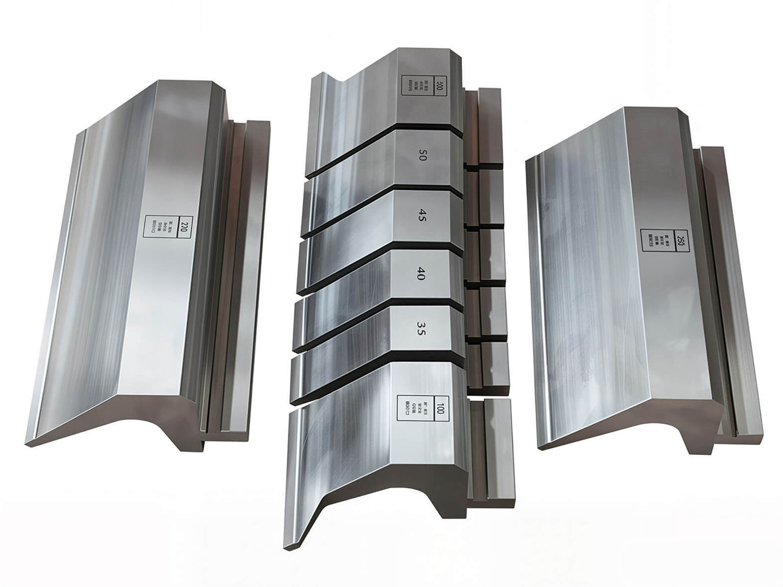
Segmented Tooling Must Be Considered in Conjunction with a Quick-Clamping System
Segmented tooling is best used in conjunction with a quick-clamping system to maximize work efficiency. In applications with frequent changeovers, standard quick clamps, hydraulic quick clamps, or pneumatic quick clamps should be prioritized. At the same time, segmented tooling must be managed through tool numbering and batch tracking; new and old segmented tooling must not be mixed. For frequent tool changes, the quick clamping system must match the punch tang, safety groove, locking direction, and load-bearing surface.
Segmented tooling can truly save time only if the clamping system can lock the tools quickly, consistently, and uniformly. If the clamping system is inadequate, the more sections there are, the more labor-intensive it becomes to manually tighten the screws.
Box bending cannot be reduced to simple formulas; interference checks are mandatory
When bending box-shaped parts, it is not sufficient to simply calculate the upper punch height. In actual machining, the box depth, return flange length, gooseneck throat depth, punch height, open height, bending sequence, and part removal direction all affect whether the workpiece and die will collide.
The most reliable method is to simulate the entire bending process based on the product drawings to check whether the workpiece and die will collide at each step of the process.
What Causes Press Brake Tooling Mismatch Failures?
Once tooling is mismatched, it can lead to problems such as failure to install, unstable clamping, centerline deviation, unstable angles, and tool damage. When troubleshooting, you must strictly follow the sequence: “Clamping fit → Centerline → Die holder → Segmented tooling → Tonnage load.”
Causal Table of Mismatch Consequences
|
Consequences |
On-site performance |
Root causes |
Corresponding inspection items |
|---|---|---|---|
|
Cannot be installed |
The punch tang won’t insert; the safety groove is jammed; the lower die won’t fit into the die holder |
Different standards |
clamping standard, tang, die base |
|
Unstable clamping |
Operates normally under no-load conditions, but slips after bending with material |
Clamping surfaces do not align; locking mechanisms do not match |
upper clamp, bearing shoulder |
|
Off-center |
There is angle inconsistency from side to side on the workpiece; there are indentations on one side |
The punch tip and the V-opening center do not align |
centerline, adapter, die holder |
|
Unstable angle |
Angles fluctuate between large and small within the same program |
Incorrect tool height; different heights for segmented tooling; uneven clamping |
tooling data, segmented fit |
|
Tooling damage |
The die has notches, dents, or wear on one side |
Excessive tonnage; V-die opening too small; off-center loading |
load capacity, V opening |
|
Damage to machine components |
Damage to the clamp; dents on the die holder; wear on the guide rails |
Prolonged off-center loading or overload |
clamping fit, centerline, tonnage |
On-Site Troubleshooting Sequence
When a misalignment issue occurs, follow this sequence to troubleshoot:
Do not start by adjusting the CNC parameters right away. If fundamental issues such as unstable die clamping, misaligned tooling centerlines, or inconsistent heights of segmented tooling remain unresolved, even the best-optimized program will be ineffective.
The 5 Most Common Mistakes
Mistake 1: Forcing American 12.7 mm tooling into a European 13 mm clamping system
Although the difference appears to be only 0.3 mm, it actually causes significant errors and directly alters the clamping and positioning locations.
Mistake 2: Focusing only on the upper punch, not the die holder
The upper punch may clamp securely, but if the die V-opening centerline is misaligned, the angle will still be out of specification.
Mistake 3: Not recalculating the working height after using an adapter
The adapter occupies space within the open height, making it easy for collisions to occur or for workpieces to become stuck when bending deep boxes or bent parts with return flanges.
Mistake 4: Purchasing segmented tooling without upgrading the clamping system
Without a quick-clamping system, the more segments a tooling system has, the more time it takes to manually lock it in place.
Mistake 5: Assuming the die is sufficient just because the machine has enough tonnage
Just because the machine can bend a part does not mean the die, lower die holder, and clamping system can all withstand that force.
Overloading does not just damage the die; it affects the entire machine structure
A common point of misunderstanding: The tonnage listed on the nameplate does not mean the machine can bend at full tonnage at any position or along any length.
The actual tonnage a press brake can utilize is limited by multiple factors, including the bending position, bend length, off-center loading conditions, the die’s maximum load capacity, and the manufacturer’s operating manual. When bending short parts, off-center parts, thick plates, or small V-die openings, the line load capacity per meter must be calculated separately.
Furthermore, the tooling load capacity often reaches its limit before the press brake’s tonnage does. For example, if a machine has a bending capacity of 200 metric tons but the die’s load capacity is 100 metric tons per meter, then the punch, die, clamping system, and lower die holder cannot be operated at 200 metric tons. When making a practical assessment, the key consideration is how the bending force is distributed across the length of the die—specifically, whether the linear load per meter exceeds the die’s load capacity.
When bending short parts, it is even more important to pay attention to the tooling load capacity. Returning to the previous example, suppose the bending force is 30 metric tons applied over a bend length of 200 mm; the linear load per meter would be 150 metric tons per meter. Although this does not appear to exceed the machine’s rated tonnage, the linear load per meter has already exceeded the tooling’s rated load capacity of 100 metric tons per meter. This can cause damage to the lower die edge, uneven stress distribution on the clamps, and, in severe cases, leave indentations on the die holder or bed.
How to Choose a Compatible Tooling System for Your Application?
The press brake tooling system must be configured based on the product structure, tool change frequency, material load, bend length, and precision requirements—it is not simply a matter of choosing the cheapest option.
Standard Sheet Metal Parts
For standard sheet metal parts, a configuration combining a CNC press brake, European-style tooling, a basic quick clamp, common V-dies, and a small number of segmented upper punches is generally recommended. This setup is ideal for bending mild steel, medium-to-thin sheets, and standard flange parts, and is suitable for applications with infrequent tool changes and moderate bend angle accuracy requirements.
Electrical Enclosures, Cabinets, and Housings
For electrical enclosures, cabinets, and housings, a configuration combining segmented tooling, gooseneck punches, and a quick-clamping system is generally recommended. Sufficient open height and throat depth must be ensured, and it is essential to verify in advance that the workpiece will not collide with the dies or the machine body.
High-Variety, Low-Volume Workshops
High-variety, low-volume workshops generally opt for a configuration combining segmented tooling, a quick-clamping system, common-height tooling, staged bending setup, and offline programming. Segmented tooling must be numbered and managed to prevent mix-ups. The goal in such workshops is not to maximize the speed of a single bend, but to minimize the time spent on tool changes and bending programs as much as possible.
Thick Sheet Metal, Stainless Steel, and High-Strength Steel
For thick sheet metal, stainless steel, and high-strength steel, the most critical consideration is whether the dies and machine can withstand the bending forces over the long term. The following configurations must be checked in the following order:
First, check the tooling load capacity; next, check the V-die opening size; then, check the load capacity of the lower die holder and the crowning table; and finally, check the long-term load capacity of the clamping system.
Replacing Old Dies with New Machines
When installing old dies on a new press brake, pay attention to the following points:
First, measure the dimensions of the old dies; then, check for wear, ensure the dies are straight overall, and verify the centerline position; finally, determine whether they can continue to be used, whether an adapter is needed, or whether the entire tooling system should be replaced.
Do not continue to blindly use old dies simply to save money. If the old dies are severely worn, they will affect the bending accuracy of the new CNC press brake.
How to Specify Tooling Compatibility When Buying a New Press Brake?
When purchasing a CNC press brake, do not simply provide the tonnage and length; you must also provide the manufacturer with your current die specifications, press brake clamping system, sheet thickness, product drawings, and the expected frequency of future tool changes.
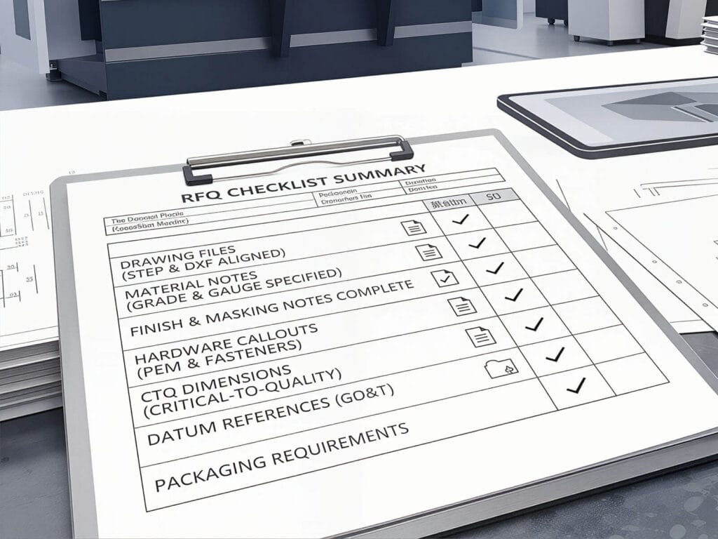
10 Pieces of Information for Suppliers
When sending an inquiry, you should provide the supplier with the following information:
Only after providing this information to the supplier can they determine whether the machine, clamping system, die holder, and dies are truly compatible.
Essential Information in the Technical Proposal
Before purchasing a press brake, the following information must be clearly specified:
Only by clearly specifying this information can you determine whether production can begin immediately upon the machine’s arrival at the factory.
What Not to Ask Suppliers
When making an inquiry, avoid asking only:
Instead, ask:
Send the supplier photos of your existing dies, the punch tang width, photos of the lower die holder, common sheet thicknesses, and bending drawings so they can determine which press brake is best suited for your specific operating conditions.
Conclusion
To ensure that a press brake can truly produce quickly and stably, you should not wait until the machine arrives at the factory to look for matching tooling; instead, you must finalize the tooling system, clamping fit, die holder, and segmented tooling plan during the procurement phase.
If you are planning to purchase a new press brake, first confirm the following:
Please send us details regarding your material, sheet thickness, bend length, product drawings, photos of your existing dies, and tool change frequency. Based on this information, Raymax can match you with the appropriate CNC press brake, upper clamp, die holder, crowning system, punch and die package, and segmented tooling plan. This ensures that once the machine arrives at your facility, you can immediately begin stable production of your products.
Ready To Upgrade Your Metal Fabrication Line?
Email Us For A Free Consultation.
Frequently Asked Questions (FAQs)
Related Blog
-1024x768.jpg)
10 Common Press Brake Air Bending Problems: Causes, Troubleshooting, and Fixes
a guide to 11 Types of press brake bending process
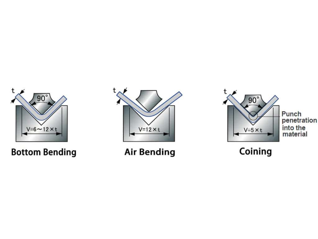
Air Bending vs Bottom Bending vs Coining: Which Press Brake Bending Method Is Right for You?
An Overview of Electric Press Brake Machines and Purchasing Tips
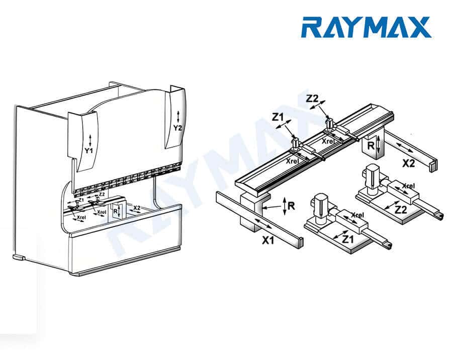
CNC press brake axis: Mastering Configurations from 2-Axis to 8+1 for Pro Results
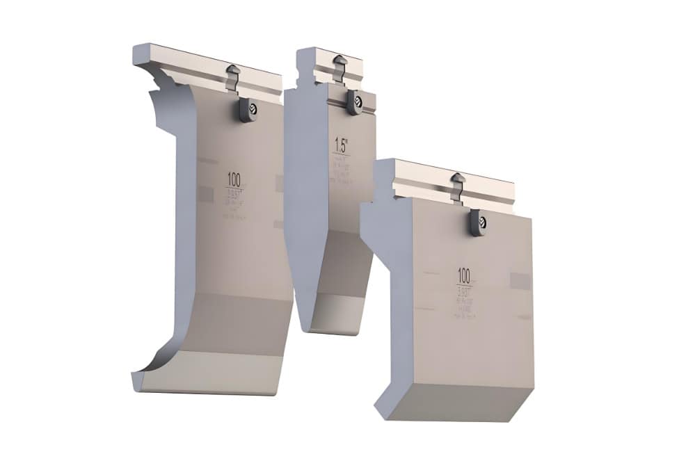
Definition of press brake tool material
Electrical Enclosure Bending: Flat Pattern, Flange Accuracy & Fit-Up Issues
How Does an Electric Press Brake Work? Working Principle, Core Parts and Pros
How to Choose a Press Brake Control System? Function, Brand & Buying Guide (Including Delem/ESA)
-1024x768.jpg)
How to Improve Press Brake Bending Consistency: Causes, Checks & Solutions
-1024x768.jpg)
How to Measure Press Brake Bending Angle: Tools, Methods & Calibration Pitfalls
How to Reduce Springback in Press Brake Bending (SS/AL/MS Checklist)
Post Your Review
Share Your Thoughts And Feelings With Others
22 responses to “Press Brake Tooling Compatibility Guide: Punch & Die Standards, Segmented Tools & Clamping Fit”
Your post offered a clear perspective on the topic while browsing online and I look forward to reading more from you
Great information shared.. really enjoyed reading this post thank you author for sharing this post .. appreciated
hocam gayet açıklayıcı bir yazı olmuş elinize emeğinize sağlık.
I very delighted to find this internet site on bing, just what I was searching for as well saved to fav
Daha önce araştırıp pek Türkçe kaynak bulamadığım sorundu Elinize sağlık eminim arayan çok kişi vardır.
Konular mükemmel olduğu gibi site teması da içeriğe müthiş uyum sağlamış. Tebrikler
Great information shared.. really enjoyed reading this post thank you author for sharing this post .. appreciated
hocam gayet açıklayıcı bir yazı olmuş elinize emeğinize sağlık.
çok bilgilendirici bir yazı olmuş ellerinize sağlık teşekkür ederim
sitenizi takip ediyorum makaleler Faydalı bilgiler için teşekkürler
I just like the helpful information you provide in your articles
Bilgiler için teşekkür ederim işime son derece yaradı
Great information shared.. really enjoyed reading this post thank you author for sharing this post .. appreciated
websitem için çok işime yaradı teşekkür ederim
I am truly thankful to the owner of this web site who has shared this fantastic piece of writing at at this place.
I found several useful ideas to consider this morning and I look forward to reading more from you
This writeup provided several useful ideas to consider while browsing online and I look forward to reading more from you
I really appreciated valuable insight into this subject this morning and I look forward to reading more from you
This writeup provided several useful ideas to consider during my research and I look forward to reading more from you
This article gave me good reasons to explore the topic further while browsing online and I look forward to reading more from you
I really appreciated a simple explanation of a complex idea today and I look forward to reading more from you
I just like the helpful information you provide in your articles