
Francis Pan
Francis Pan is the Foreign Trade Manager of RAYMAX, with over 10 years of experience in sheet metal fabrication equipment and CNC machinery. He has worked closely with manufacturers worldwide on press brakes, fiber laser cutting machines, fiber laser welding machines, and practical production-oriented metal processing solutions.
Top Guidelines
-1024x768.jpg)
-1024x768.jpg)
-1024x768.jpg)
-1-1024x768.jpg)
Table Of Contents
Stay in the the loop
Subscribe To Our Newsletter
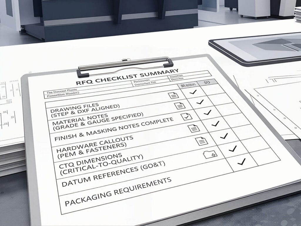
What should be checked before accepting a press brake?
During factory trials, many people focus solely on the “bend angle of the first piece.” If the bend appears precise, they often sign off on the machine hastily. However, a perfect first piece does not necessarily indicate strong batch production capabilities; what truly determines the value of the equipment is its consistency in batch production. If you are still selecting the machine, start with this guide on how to spec a press brake for tolerance before using the final acceptance checklist.
When accepting equipment, we must pay close attention to the following key indicators:
|
Test Items |
Key Metrics |
Importance |
|---|---|---|
|
Angular accuracy |
Center-angle deviation of a single workpiece |
Determines the final assembly and appearance of the workpiece |
|
Angular consistency over full length |
Left, center, and right angles of long workpieces |
Determines the assembly consistency of long workpieces |
|
Dimensional accuracy |
Flange length accuracy |
Directly determines the dimensional acceptance rate of the workpiece |
|
Geometric accuracy |
Bend straightness |
Determines whether long workpieces will become “bow-shaped” |
|
Repeatability |
Repeat positioning deviation of the back gauge and ram |
Determines whether the machine can produce 1,000 pieces continuously without scrap |
|
Stability |
Stability in batch production |
Tests the machine’s reliability under continuous production conditions |
Before the Inspection: Standardized Test Conditions
Why must test conditions be standardized?
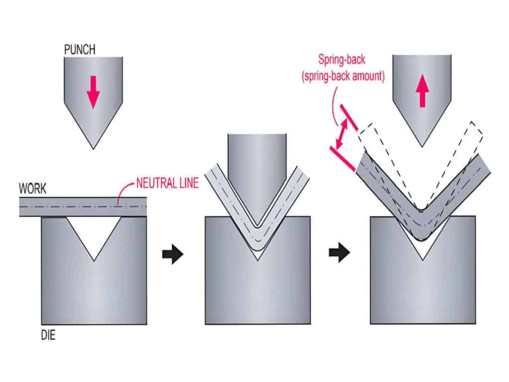
Even when using the same press brake, variations in material, sheet thickness, grain direction, tooling, and bending processes can cause fluctuations in springback, leading to differing results. Comparing accuracy without standardizing test conditions essentially means comparing bending results under different operating conditions rather than the machine’s true accuracy.
Recommended standardized test conditions
Note: We strongly recommend using cold-rolled carbon steel (such as SPCC/Q235 cold-rolled sheet) for machine validation testing. This is because it offers the best surface flatness, thickness tolerance, and material uniformity, thereby minimizing the interference of “material variation” on the machine’s true accuracy.
Essential measuring tools
Recommended sample size
What “reference tolerance ranges” are most important to consider during the acceptance inspection of a press brake?
The values in the table below are more suitable as reference ranges for high-end CNC press brakes during actual engineering acceptance inspections. Final acceptance should still be confirmed based on your workpiece drawing tolerances, material conditions, and application requirements.
|
Key Specifications |
Common Performance Targets for High-End Models |
|---|---|
|
Center angle tolerance |
±0.3° to ±0.5° |
|
Y-axis repeatability |
±0.01 mm |
|
Back gauge (X-axis) repeatability |
±0.01 mm |
|
Full-length straightness deviation |
<0.2 mm/m |
The precision values listed above are reference standards for high-end CNC machines under ideal conditions. Actual production tolerances may be affected by material springback characteristics, variations in tensile strength within the same batch, tooling wear, and the operator’s material-handling techniques. Please be sure to define the final acceptance criteria based on your specific workpiece drawings and material grades. For formal FAT/SAT sign-off, these reference values should be recorded in a press brake acceptance test checklist with the test material, target values, actual values, measuring tools, and deviation results.
10-point inspection checklist for press brake accuracy acceptance
For the full logic behind these checks, see our diagnosis flowchart for bend angle problems.
Category 1: Angular accuracy
Center bend angle
End-to-end angle consistency
Category 2: Dimensional and positioning accuracy
Flange length accuracy
For multi-bend cabinet parts, flange length errors can quickly turn into door-gap problems, hole misalignment, and assembly fit-up issues. See our guide to electrical enclosure flange accuracy and fit-up issues for a more application-specific troubleshooting process.
Back gauge repeatability
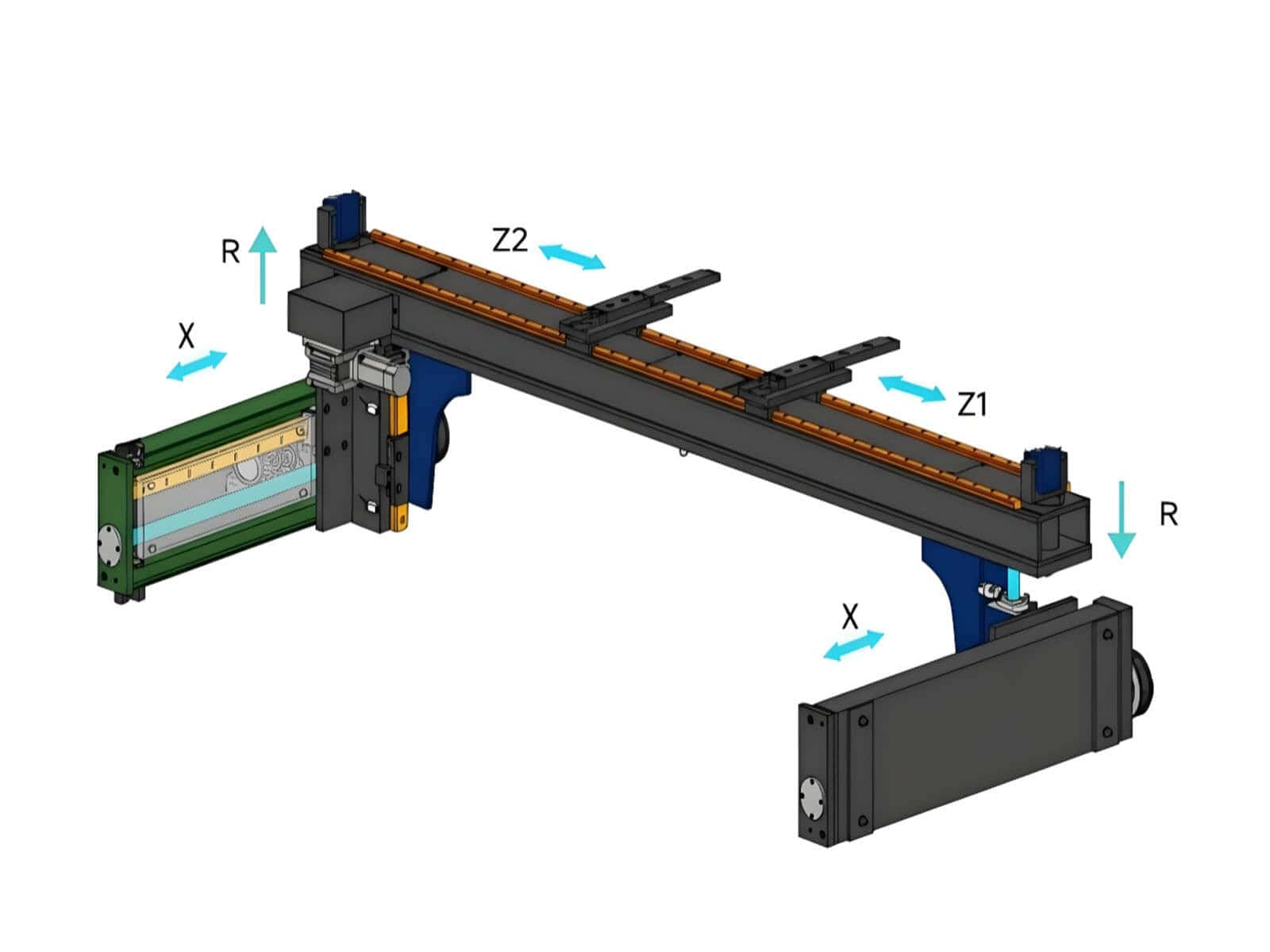
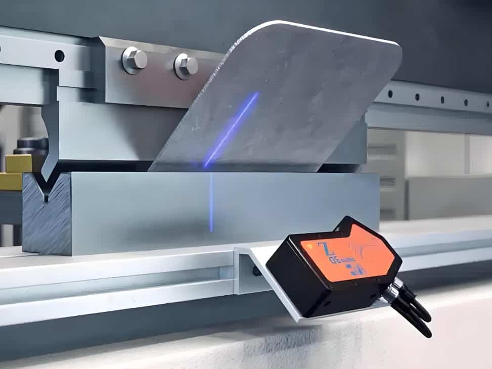
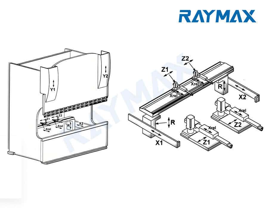
Z-axis and R-axis positioning accuracy
The positioning accuracy of the Z-axis (left-right movement) and R-axis (up-down movement) determines the precision of positioning during complex multi-step bending operations.
Category 3: Straightness and machine geometry
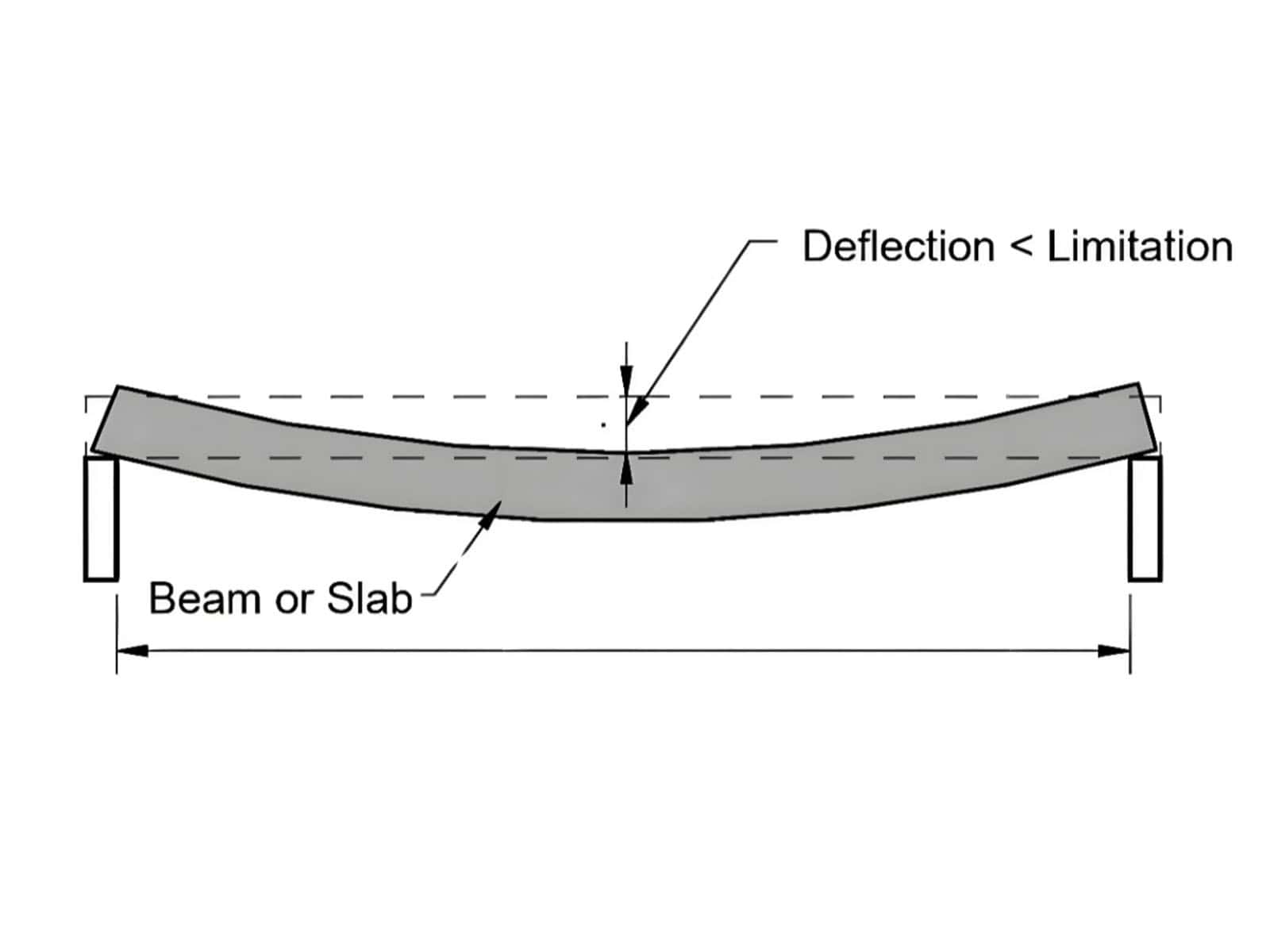
Bend straightness / Bowing
Ram-to-bed parallelism
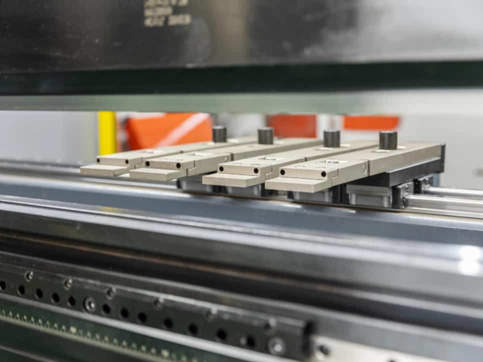
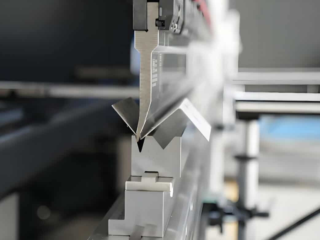
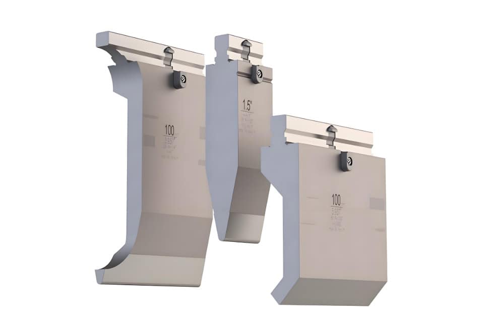
Punch and die centering and alignment
Category 4: Dynamic Performance and Production Stability
Y-axis ram repeatability
Continuous production stability / Deflection performance under full load
How should the standard bending repeatability test be conducted?
Step 1: Secure the material and tooling
Use material from the same batch, of the same thickness, and with the same rolling grain direction, and secure a set of punches and dies.
Step 2: Determine the target angle and key dimensions
Before testing, determine a target angle and at least one flange dimension that requires close measurement.
Step 3: Bend 5–10 standard test pieces consecutively
Run the same CNC program continuously to bend 5–10 test pieces, without changing any parameters during the test.
Step 4: Measure angles, lengths, and straightness
When inspecting the test specimens, record the left, center, and right angles, as well as the critical flange length and straightness, for each workpiece.
Step 5: Calculate the range and determine whether the test passes
Identify the maximum and minimum values for each indicator, calculate the difference between them, and check whether the result falls within the acceptable tolerance range. Also, assess whether there is a trend of values becoming increasingly larger or smaller. Based on these findings, determine whether the test passes.
Why does a beautiful first piece not necessarily mean the machine is suitable for batch production?
When many suppliers demonstrate the first piece during a trial run, the bent workpieces may appear highly accurate. However, once you begin batch production after purchasing the equipment, you may find that repeatability is very low. What causes this? Here are five hidden “killers” you may encounter during batch production:
Slower hydraulic response as oil temperature rises
When the machine is first started, the oil temperature is low and the hydraulic valves respond quickly, allowing the machine to maintain high precision. However, after several hours of continuous operation, the oil temperature rises, and the hydraulic valves may respond more slowly, resulting in inaccurate depth control along the Y-axis.
Inaccurate back gauge positioning due to wear on low-cost ball screws
During initial testing, new ball screws ensure more precise positioning of the back gauge. However, after several months of continuous use, low-cost ball screws wear out more quickly, which can lead to deviations in the back gauge’s repeatability.
Stress deformation caused by insufficient frame rigidity
When the machine operates continuously at full capacity, the frame is subjected to significant mechanical tensile stress and temperature rise over extended periods. If the frame has not undergone comprehensive structural rigidity design, heavy-duty welding, and thorough stress-relief annealing (to eliminate internal stresses) prior to shipment, it may develop minute, permanent “plastic deformation” under prolonged high stress. This will result in bending angles and straightness that can never be restored to factory specifications, regardless of how you adjust the parameters.
Unstable crowning response
Inexpensive crowning systems may produce inconsistent compensation values after each load application, resulting in angular deviations at both ends and in the middle of long workpieces.
Amplification of errors due to material batch variations
If the machine is unstable, any fluctuations in material properties, thickness, or grain direction will amplify errors in the finished product, leading to an increase in scrap rates.
Therefore, the reason a high-end press brake can guarantee long-term batch precision lies in its high-quality hydraulic system, stable feedback system, high-rigidity annealed frame, and more reliable back gauge structure. In the configuration of its high-precision models, Raymax places greater emphasis on ensuring machine performance through batch stability, rather than relying solely on data from individual demonstrations.
When purchasing a press brake, what accuracy verification documents should buyers request from suppliers?
It is recommended that buyers request the following documents from suppliers prior to purchase:
If you request these reports from the manufacturer and they are unable to provide them, then no matter how high the precision demonstrated during the on-site first-piece demonstration, it does not guarantee stable and reliable performance during batch production.
How does Raymax validate this inspection logic before shipment?
At Raymax, we place greater emphasis on verifying the angles, dimensions, and repeatability of batch-produced parts prior to shipment, rather than simply presenting a first-article sample. To ensure more consistent batch quality, we also apply stricter criteria when selecting components.
Download the printable press brake accuracy checklist
To make your on-site inspection easier, we have prepared a PDF version of the press brake accuracy checklist. Please enter your email address below to download and print it for free.
If you need further assistance in selecting a high-precision press brake, please feel free to send us your drawings. Raymax engineers will provide you with free test bending samples and a machine selection plan.
Ready To Upgrade Your Metal Fabrication Line?
Email Us For A Free Consultation.
Frequently Asked Questions (FAQs)
Related Blog
-1024x768.jpg)
10 Common Press Brake Air Bending Problems: Causes, Troubleshooting, and Fixes
a guide to 11 Types of press brake bending process
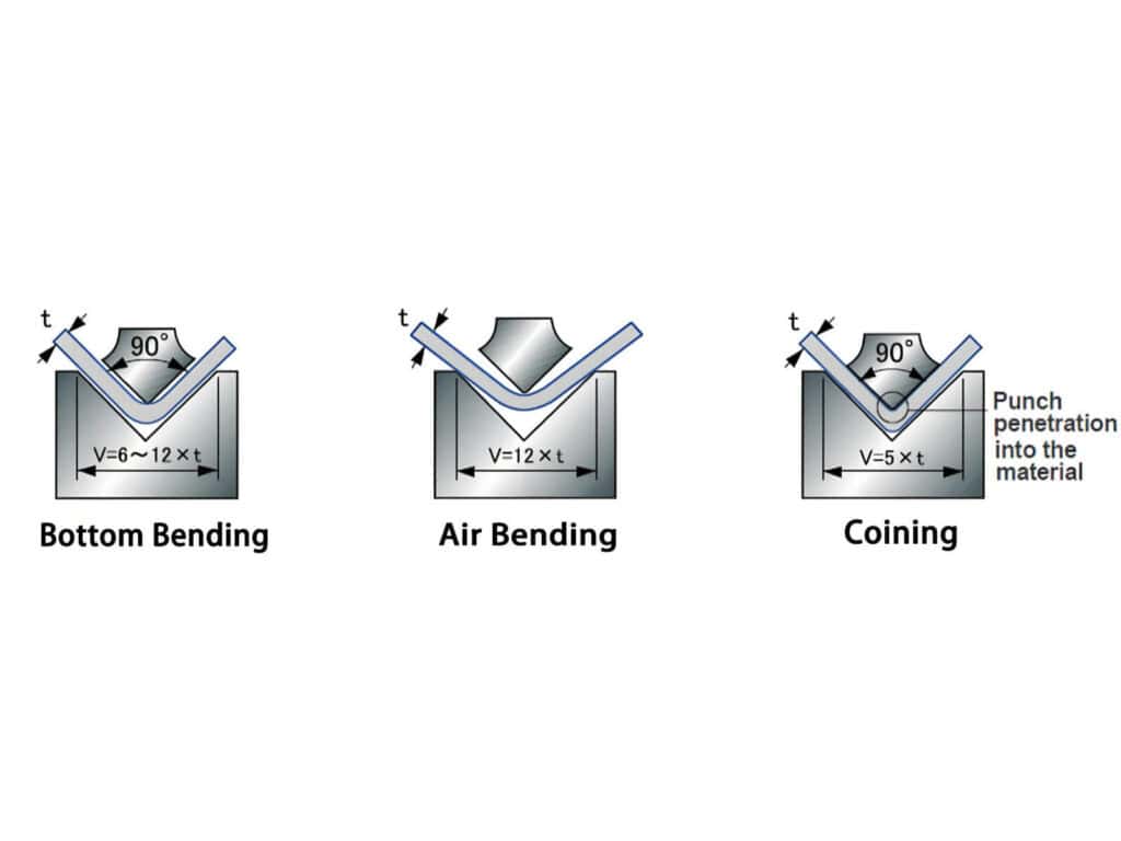
Air Bending vs Bottom Bending vs Coining: Which Press Brake Bending Method Is Right for You?
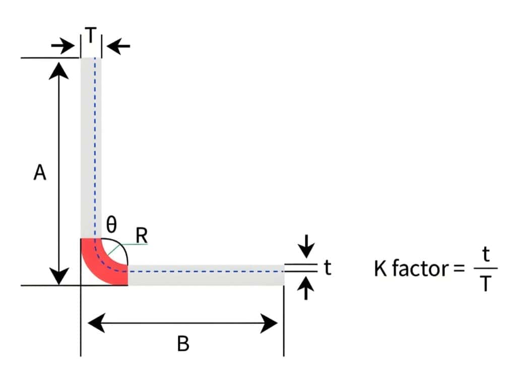
Bend Allowance vs Bend Deduction vs K-Factor: How to Calculate Sheet Metal Flat Patterns (With Examples)
CNC press brake axis: Mastering Configurations from 2-Axis to 8+1 for Pro Results
Definition of press brake tool material
Electrical Enclosure Bending: Flat Pattern, Flange Accuracy & Fit-Up Issues
-1024x768.jpg)
How to Improve Press Brake Bending Consistency: Causes, Checks & Solutions
-1024x768.jpg)
How to Measure Press Brake Bending Angle: Tools, Methods & Calibration Pitfalls
How to Reduce Springback in Press Brake Bending (SS/AL/MS Checklist)
How to Spec a Press Brake for Tolerance: Angle, Flange Length, Crowning, Backgauge & Acceptance Checklist
How to Use a Press Brake Machine for Precise Bending
Post Your Review
Share Your Thoughts And Feelings With Others