
Francis Pan
Francis Pan is the Foreign Trade Manager of RAYMAX, with over 10 years of experience in sheet metal fabrication equipment and CNC machinery. He has worked closely with manufacturers worldwide on press brakes, fiber laser cutting machines, fiber laser welding machines, and practical production-oriented metal processing solutions.
Top Guidelines
-1024x768.jpg)
-1024x768.jpg)
-1024x768.jpg)
-1024x768.jpg)
Table Of Contents
Stay in the the loop
Subscribe To Our Newsletter
Introduction
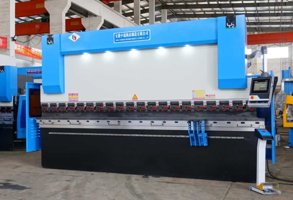
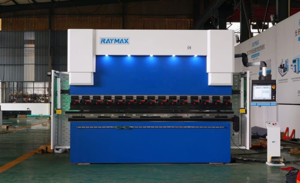
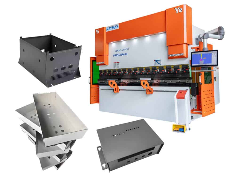
CNC press brake is a kind of press brake controlled by computer numerical control system. It can bend metal plates into various shapes. It is suitable for complex and high-precision material processing and batch production. Among them, CNC axis is the core configuration to ensure the bending accuracy and efficiency of CNC press brake. Each axis plays a key role in improving the accuracy of bending. Therefore, it is important to understand these axes to optimize the performance and accuracy of the press brake. In this article, we will explore the wonderful world of CNC press brake axis from the aspects of axis definition, how to select appropriate axis configuration, common problems, etc.
What is CNC press brake axis?
What is the press brake back gauge?
The back gauge is installed behind the press brake. It is an important part used to help locate and support the workpiece during bending processing. Its existence can make each bending meet the bending requirements and reduce the rework rate caused by errors. The accuracy and flexibility of the back gauge can help us greatly improve the bending production efficiency and ensure the quality of the finished workpiece.
Accurate definition of “axis” of press brake
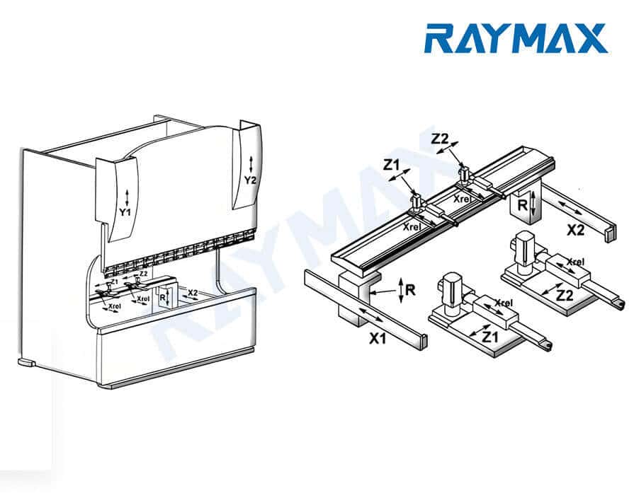
The axis in the press brake is responsible for controlling the movement of different parts on the press brake in different directions. When these axes work together, the press brake can accurately complete the bending action. Through X, R, y and other multi axis cooperation, the machine can automatically adjust to the position set by the system to complete the accurate bending angle and shape of the workpiece.
Axis naming rules and common differences
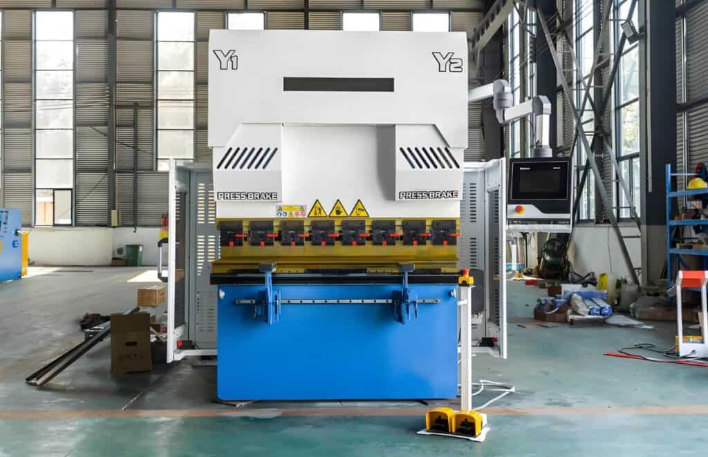
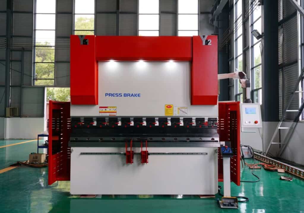
1. single Y and y1/y2
Single Y: common in old-fashioned or economical torsion bar synchronized press brake. It forces the left and right hydraulic cylinders to move synchronously through a torsion bar. The CNC system cannot independently adjust left/right stroke, and cannot independently adjust left/right ram stroke for tilt correction.
Y1/Y2: commonly used in electro-hydraulic servo synchronous (or high-end synchronous control) press brakes, it indicates the independent position closed-loop control on the left and right sides of the ram, usually corresponding to the left and right cylinder circuits. Y1 and Y2 respectively control the downward pressing or return displacement of the ram on both sides, maintain the left-right parallelism of the ram, compensate for the eccentric load when the bending load is uneven, and ensure the consistency and repeatability accuracy of the bending angle.
2. Writing differences of x/x1/x2, r/r1/r2 and z/z1/z2
Y1/Y2: commonly used in electro-hydraulic servo synchronous (or high-end synchronous control) press brakes, it indicates the independent position closed-loop control on the left and right sides of the ram, usually corresponding to the left and right cylinder circuits. Y1 and Y2 respectively control the downward pressing or return displacement of the ram on both sides, maintain the left-right parallelism of the ram, compensate for the eccentric load when the bending load is uneven, and ensure the consistency and repeatability accuracy of the bending angle.
The number of axes from different manufacturers may be slightly different. For example, some European brands may call the main pressure axis y-axis, while some Japanese brands may have specific axis codes on special models. However, the motion logic of most axes basically conforms to the general standard of “x-front and rear, y-pressure, r-up and down, z-left and right”.
Detailed explanation of the main axis of the press brake
|
Axis name |
Control object |
Problems solved |
Typical working conditions |
|---|---|---|---|
|
Y & y1/y2 |
Ram up and down, left and right synchronization |
Left and right synchronous control, improved long workpiece consistency and more stable repeatability accuracy |
Long workpiece, thick plate, batch parts with high requirements for angle consistency |
|
X & x1/x2 |
Backgauge front/back positioning (flange length control) |
Complex process of independent positioning and asymmetric realization |
Multi specification model change, tight dimensional tolerance and batch positioning |
|
R & r1/r2 |
Upper and lower height of back gauge finger |
Quick adjustment of backgauge fingers height, workpiece turnover / smoother multi process |
U-shape, box type, multi-stage bending and flanging |
|
Z & z1/z2 |
The backgauge fingers move left and right to control the width |
Positioning of asymmetric parts, multiple positioning points and rapid adaptation to different widths |
Suitable for asymmetric parts, multiple locating points and complex workpieces |
|
V |
Deflection compensation |
Improve the consistency of bending angle, reduce trial bending and improve the yield |
The longer the length and the larger the tonnage, the more obvious, especially for the side plate of the long box |
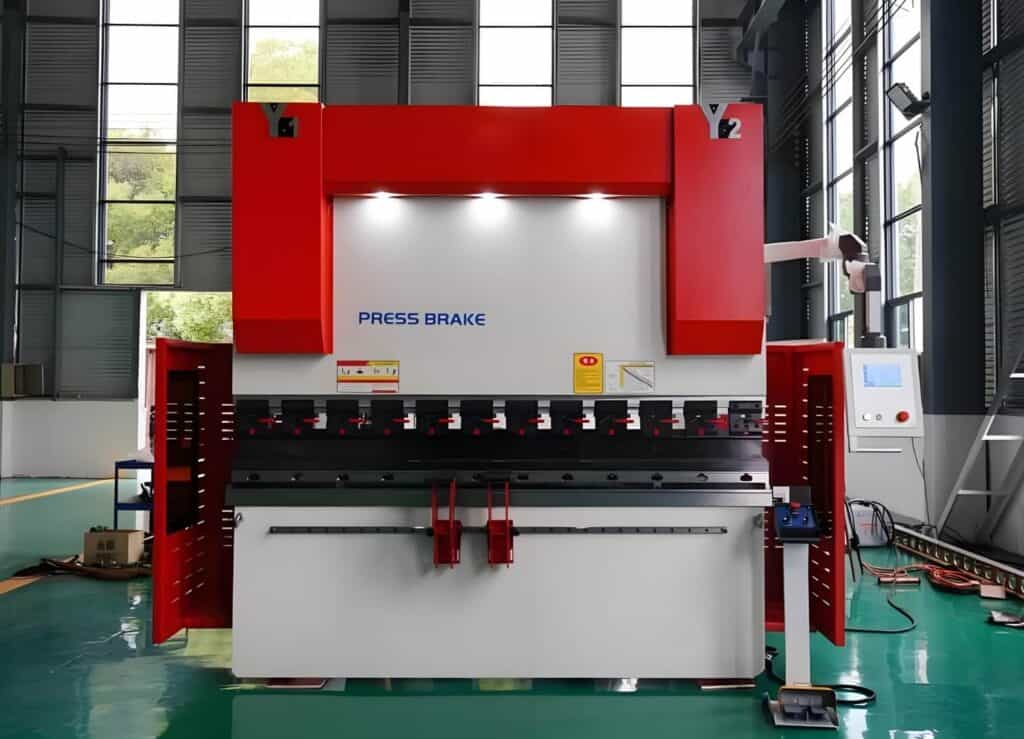
Y-axis (Y1/Y2)
Control the up and down movement of the ram on both sides, with each up and down movement linked to precision and consistency.
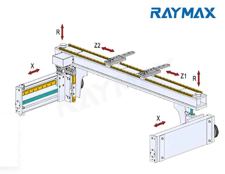
X-axis
Front and rear axis of back gauge): It guides the forward and backward movement of the back gauge and is the core of the bending length and positioning size.
R axis (upper and lower axis of back gauge)
The R axis is mainly responsible for driving the back gauge finger to move accurately in the vertical direction. It is used to control the height of the back gauge and is suitable for bending inclined parts or customized workpieces with height differences.
What does the R axis solve:
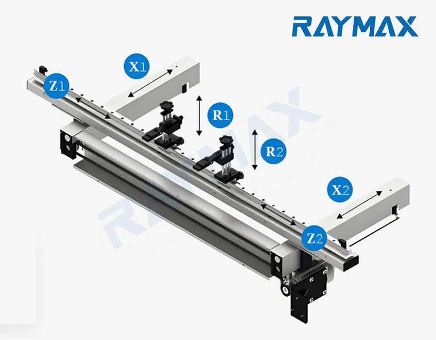
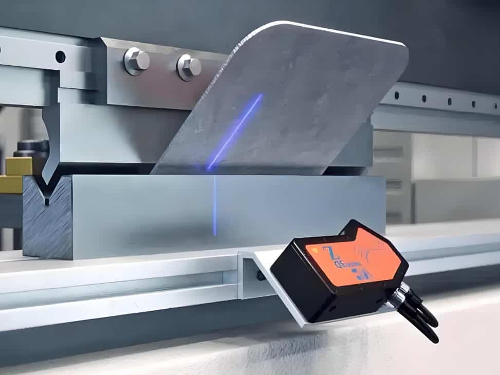
Z-axis (Z1/Z2 left and right axes)
Controls the left and right movement of the back gauge, and the Z-axis is particularly useful for bending or handling asymmetric workpieces with significant changes in machining position.
Z-axis function: The Z-axis controls the movement of the back gauge finger in the left and right directions. The most basic function is to adjust the spacing between two backgauge fingers based on the width of the workpiece, in order to stably position the workpiece.
Value of Z1/Z2:
V-axis
Crowning/deflection compensation): responsible for compensating for the deflection generated by the machine tool bed during the bending process, reducing the angle difference between the middle and both ends of the long workpiece.
Why compensation is needed:
According to material mechanics, any beam will bend under stress, and press brakes are no exception. When the ram is pressed down, the huge bending force will cause both the ram and the bed below to produce small, invisible downward bends, that is, deflection. This deformation will cause the distance between the punch and die in the middle of the machine to be larger than the two ends, resulting in longer bent workpieces with a larger angle in the middle than at the two ends. The longer and thicker the sheet, the more obvious this phenomenon becomes. Therefore, a V-axis is needed to compensate for the deflection generated by the machine tool bed during the bending process.
The benefits brought by the V-axis:
Common axis configurations and their meanings
Note: Axis naming and axis counting can vary by brand and controller. Always confirm the Controlled Axes list and the backgauge axis diagram in the official specification.
How to read the axis configuration: 2 axes, 3+1, 4+1, 6+1, 8+1 logic
Manufacturers usually use “N+1” to represent the number of axes.
Configuration Comparison Table
The names, capability profiles, and usage scenarios of different axis configurations are as follows:
|
Configuration Name |
Typical includes axis |
Capability Profile |
Applicable scenarios |
|---|---|---|---|
|
2 axes |
Y + X |
Basic bending with backgauge positioning |
The most basic model. Suitable for basic parts, standard parts, simple bending, and low efficiency requirements for changeover |
|
3+1 axis |
Y1/Y2 + X + V |
Left and right synchronization+deflection compensation, significantly improving angle consistency |
Standard precision press brake. Suitable for batch long workpieces with high requirements for angle consistency |
|
4+1 axis |
Y1/Y2 + X + R + V |
Added automatic adjustment of backgauge fingers height for better efficiency in processing complex parts |
Mainstream configuration in the industry. Suitable for workpieces with box, U-shaped, multi pass bending, and high interference |
|
6+1 axis |
Y1/Y2 + X + R + Z1/Z2 + V |
Add left and right independent positioning, stronger for asymmetric parts/multiple positioning points |
Advanced configuration. Suitable for complex processes and mixed production of large and small parts |
|
8+1 axis |
Y1/Y2+ X1/X2 + R1/R2 + Z1/Z2 + V |
Two backgauge fingers are independent of each other on three axes, with full positioning freedom |
Top of the line model. For irregular parts, beveled edges, and heavy-duty multi-stage molds |
For buyers comparing 4+1, 6+1, and 8+1 configurations, our 6 axis press brake guide explains the working principles, advantages, applications, and buying considerations in more detail.
Is it better to have more axes?
Not so. An increase in the number of axes usually means: more servo motors, drivers, and transmission mechanisms, higher costs, and increased maintenance complexity. For buyers comparing 3-axis, 4-axis, and 6-axis machines, it is also important to understand how backgauge axes affect press brake price before deciding whether the upgrade is worth the budget.
If your product is a simple bending with minimal size changes over the long term, choosing 4+1 axis is more than enough; If you frequently perform multi pass bending with frequent and asymmetric changes, having fewer axes will result in a large amount of manual alignment, flipping, and trial bending, leading to higher overall costs. Therefore, it is best to choose 6+1 axis or 8+1 axis. In short, the choice of axis configuration mainly depends on your machining needs.
How to choose the appropriate axis configuration
Before selecting the number of CNC axes, buyers should first confirm whether their production needs are better suited to an NC or CNC machine. If you are still comparing control systems, automation levels, accuracy requirements, and budget differences, you can read our NC vs CNC press brake guide first.
Minimum number of axes required to meet basic bending requirements
The minimum number of axes required for a press brake depends on the complexity of the bending operation, and the most basic press brake requires X and Y axes to complete simple bending tasks. The X-axis guides the forward and backward movement of the back gauge, used to position the workpiece. The Y-axis is responsible for controlling the vertical movement of the ram and applying pressure to the workpiece.
Key factors for selection
Typical application scenarios for different axis configurations
1. Simple Parts/Standard Parts
If the materials we usually process are simple parts/standard components, then our requirement for axis configuration is to achieve basic positioning and stability. The common choices are mostly 2-axis or 3+1-axis.
The triggering conditions include the following points:
If the workpiece is too long and the customer is sensitive to consistency, 3+1 (with V-axis) can reduce the end-to-end angle difference and trial bending, which is a better choice.
2. Conventional sheet metal parts/enclosures/cabinets/frequently replaced models
If the materials we usually process are some conventional sheet metal parts/box cabinets that require multiple bending and interference, and we want to improve bending efficiency, 4+1 or 6+1 axes are more suitable.
The triggering conditions include the following points:
3. Asymmetric / Complex Localization / Multiple Localization Points
If we need two independent backgauge fingers with three axes each and require higher positioning freedom, 6+1 or 8+1 is a more perfect choice.
The triggering conditions include the following points:
For these high-mix and complex bending applications, an 8 axis press brake can provide greater backgauge positioning freedom, especially when the workpiece requires independent X1/X2, R1/R2, and Z1/Z2 movement during multiple bending steps.
How to read specification sheets and quotations
Shaft related parameters that must be checked in the specification table
1. Controlled Axes List
This is the most important part, which will clearly list whether this machine includes axes Y1, Y2, X, R, Z1, Z2, V, etc. We need to carefully review and ensure that what is listed here is consistent with the sales commitment.
2. Back gauge stroke/speed/repeat positioning accuracy
3. Types of Compensation Systems
4. Control System Functions
Common Misconceptions and Avoiding Pitfalls
1. Similarly write “6+1”, different manufacturers have different axis definitions/independent methods
Some manufacturers may define 6+1 as Y1/Y2+X+R+Z1/Z2+V, while others may define it as Y1/Y2+X1/X2+R+Z+V. The latter’s Z-axis is not independent and has completely different capabilities. So we must carefully read the axis list and the specific motion diagram.
2. Has Z-axis ≠ has Z1/Z2 independent positioning
There is a significant difference in function and meaning between having a Z-axis and a Z1/Z2 axis. Many basic configuration tables will write ‘Z-axis’, but this usually refers to the linkage of two backgauge fingers and cannot independently adjust the spacing. Only by clearly stating the Z1/Z2 axes can they be independently programmed and moved. This is one of the most common pitfalls that leads to selection errors.
3. Only looking at the number of axes without considering the stroke/accuracy/structure can easily make it look high-end but not easy to use
The more axes a press brake has, the better its usability does not necessarily mean it is more useful. It depends on the back gauge travel, repeat positioning accuracy, and structural rigidity of the press brake. For example, a 4+1 axis machine with a high-precision grating ruler, fast ball screw, and powerful servo motor may have much higher production efficiency and finished product quality than a 6+1 axis machine with a regular configuration and slow screw.
What are the global standards and regulations that affect the design of press brake axes?
Safety is the first element of production, and the design of press brakes is influenced by safety regulations in different regions.
Common problems and maintenance strategies of axis system
Common problems with multi axis CNC Press Brake
1. Back gauge misalignment
Common reasons:
Solution:
2. Inconsistent bending angles
Common reasons:
Solution:
3. Axis control failure
Common reasons:
Solution:
4. Excessive wear of mechanical components
Common reasons:
Solution:
5. Hydraulic Leakage
Common reasons:
Solution:
Standard procedures for daily maintenance, preventive maintenance, and axis zero-point calibration
Daily maintenance:
Preventive maintenance (weekly/monthly):
Axis zero point verification:
Summary
CNC bending axes can manufacture high-precision parts with high efficiency, greatly improving the economic benefits of factories. Different axes are influenced by various factors such as materials, back gauges, and budget. Whether you use Y1 and Y2 axes for ram movement or Z1 and Z2 axes for precise back gauge positioning, each axis is crucial for producing high-precision and high-quality finished products. We need to choose the appropriate axis configuration based on the material, thickness, length, and process requirements of the workpiece. If you have any purchasing needs, please feel free to contact RaymaxTech. You can send us your workpiece drawings, materials, dimensions, etc. We will provide you with customized solutions for axis selection and professional technical consultation.
Ready To Upgrade Your Metal Fabrication Line?
Email Us For A Free Consultation.
Frequently asked questions (FAQs)
Related Blog
Press Brake Tooling Compatibility Guide: Punch & Die Standards, Segmented Tools & Clamping Fit
Press Brake Price Guide 2026: Cost Factors, Options & Accurate Quotes
Tooling & Clamping for High-Mix Production: Quick Clamp vs Hydraulic Clamp vs Manual Clamp ROI
Press Brake FAT/SAT Acceptance Checklist: Accuracy Tests, Tolerance & Documentation
Press Brake RFQ Checklist: 14 Fields You Must Provide for an Accurate Quote
-1-1024x768.jpg)
How to Spec a Press Brake for Tolerance: Angle, Flange Length, Crowning, Backgauge & Acceptance Checklist
-1024x768.jpg)
Press Brake Crowning Troubleshooting: Fix Uneven Bend Angles Across Long Parts
-1024x768.jpg)
How to Improve Press Brake Bending Consistency: Causes, Checks & Solutions
-1024x768.jpg)
Press Brake Backgauge Accuracy Troubleshooting: How to Diagnose Flange Length Errors
-1024x768.jpg)
Press Brake Tonnage Comparison: Air Bending vs Bottoming vs Coining (How Force Changes + Safety Margin)
Electrical Enclosure Bending: Flat Pattern, Flange Accuracy & Fit-Up Issues
Press Brake Bending Accuracy Checklist: 10 Quantified Factors to Inspect
Post Your Review
Share Your Thoughts And Feelings With Others