
Francis Pan
Francis Pan is the Foreign Trade Manager of RAYMAX, with over 10 years of experience in sheet metal fabrication equipment and CNC machinery. He has worked closely with manufacturers worldwide on press brakes, fiber laser cutting machines, fiber laser welding machines, and practical production-oriented metal processing solutions.
Top Guidelines
-1-1024x768.jpg)
-1024x768.jpg)
-1024x768.jpg)
-1024x768.jpg)
Table Of Contents
Stay in the the loop
Subscribe To Our Newsletter
Quick Answer
The value of a 6 axis press brake does not lie in the fact that it has more axes or is more advanced, but rather in the greater positioning flexibility it offers for complex workpieces, during the machining process. For asymmetrical parts, deep-flanged parts, box-shaped parts, parts requiring multiple consecutive bends, and applications with frequent changeovers, the 6 axis press brake, thanks to its greater flexibility, can significantly reduce the need for manual adjustments and trial bends, resulting in more efficient first-piece setup, and more stable batch production.
There are various definitions of “6 axis press brakes” within the industry. The term “6-axis” used in this article primarily refers to the six axes of the entire machine, with a typical configuration being Y1, Y2, X, R, Z1, Z2. In this configuration, Y1 and Y2 control ram positioning and synchronization on the left and right sides of the ram, while X, R, Z1, Z2 control the front-to-back, height, and left-to-right backgauge positioning.
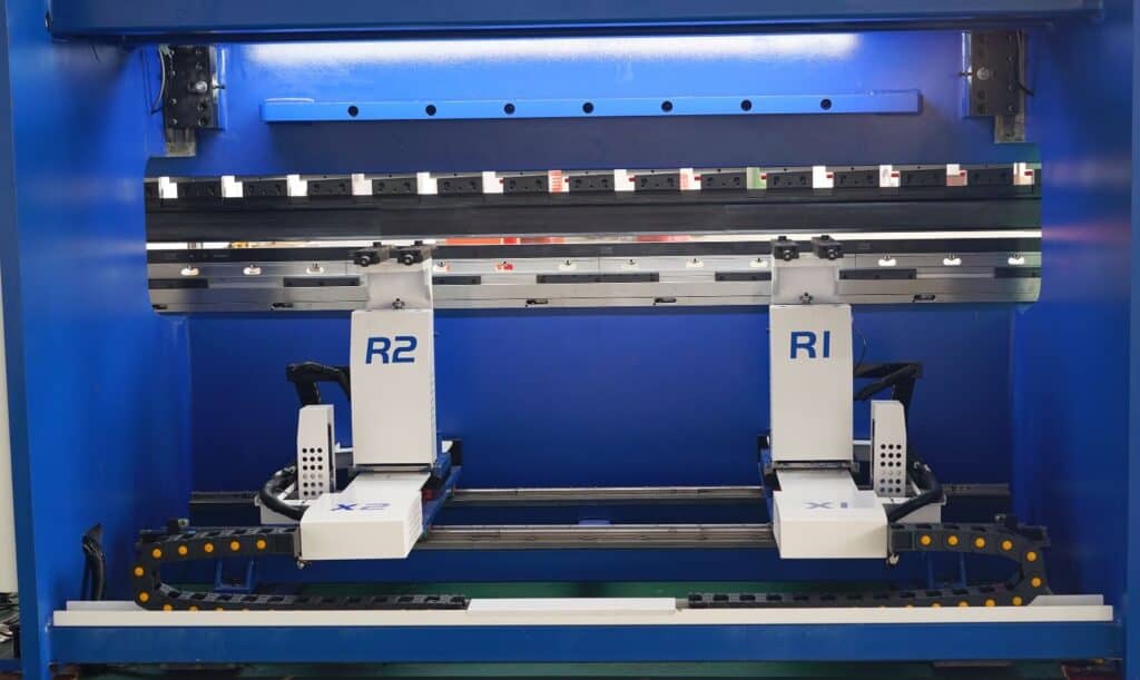
Another interpretation of “6-axis” refers to a 6-axis backgauge, with a typical configuration of X1, X2, R1, R2, Z1, Z2. When selecting a press brake, one should not rely solely on the “6-axis” label but must verify exactly which actions each axis controls.
This article will provide a detailed overview of the workflow, features, typical applications, and configuration recommendations for 6 axis press brakes, offering practical guidance for choosing the right machine.
If you are struggling to decide between a 4 axis and a 6 axis press brake, we recommend that you look beyond the number of axes and instead consider your workpiece structure, positioning reference, bending length, changeover frequency, and batch consistency requirements. You can send us your drawings, material specifications, sheet thickness, and production capacity, and RAYMAX will help you determine whether a 6 axis press brake is necessary.
What Is a 6 axis Press Brake? Axis Definitions and Common Configurations
6 Axis Press Brake: Understanding Axis Definitions and Common Configurations
Before introducing 6 axis press brakes, we must first confirm exactly what “6- axis” refers to. Since naming conventions may vary among manufacturers, focusing solely on the number of axes during procurement can easily lead to misjudgments. Additionally, in most CNC press brake applications, a 6 axis press brake is typically discussed in conjunction with electro-hydraulic servo control, backgauge positioning, ram synchronization, and crowning.
|
Definition type |
Common axis configurations |
Description |
Applications |
|---|---|---|---|
|
Full-machine 6-axis |
Y1, Y2, X, R, Z1, Z2 |
Y1/Y2 control ram positioning and synchronization on both sides of the ram; X/R/Z1/Z2 control the backgauge’s forward/backward, vertical, and lateral positioning |
Most CNC press brake manufacturers |
|
6-axis backgauge |
X1, X2, R1, R2, Z1, Z2 |
The backgauge itself has additional degrees of independent motion |
High-end complex parts, multi-reference positioning, automated bending |
|
6+1-axis |
6-axis configuration with an additional V-axis or crowning axis |
The V-axis is typically used for crowning |
Long workpieces, high-precision parts, high requirements for batch consistency |
Therefore, when purchasing, we shouldn’t just ask, “Is it a 6-axis system?” but should clarify exactly:
For a broader explanation of different machine configurations, from basic 2 axis systems to 8+1 axis setups, you can also refer to our guide on CNC press brake axis configurations.
Should you choose a 6-axis system? A 30-second decision guide
|
Workpiece characteristics |
Workpiece/Production description |
Configuration recommendations |
Reasons for judgment |
|---|---|---|---|
|
Standard symmetrical parts, single bends |
Simple structure, high repeatability |
A 3- or 4-axis configuration is sufficient |
Increasing the number of axes does not yield significant benefits; cost control is the priority |
|
Asymmetrical parts, left and right flanges do not match |
Irregular shapes, unequal left and right side lengths, inconsistent positioning references |
6-axis |
The Z1 and Z2 axes can be adjusted independently left and right, reducing the need for manual material positioning |
|
Deep-flanged parts, box-shaped parts |
Deep flanges, multi-sided bending, box-type structures |
6-axis |
The R-axis height coordinates with Z-axis positioning, reducing the risk of sheet sagging and positioning offset |
|
Long workpieces, wide sheet metal parts |
Long lengths, high requirements for angle consistency |
6-axis + crowning system |
Better control of angle differences between the center and ends of the workpiece |
|
Frequent changeovers |
Small batch sizes, wide variety of parts, frequent machine setup changes |
6-axis |
Reduces setup time for the first part and changeover time |
|
Multi-step continuous bent parts |
Multiple bending operations, risk of collisions |
6-axis + 3D simulation |
Multi-axis coordination of the backgauge reduces the risk of collisions, and 3D simulation allows for advance modeling of the bending sequence |
|
High-precision batch parts, cosmetic parts, functional assemblies |
Strict angle tolerance requirements, high demands for batch consistency |
6-axis + angle measurement system/crowning system |
Ensures high batch consistency |
Definition of a 6 axis Press Brake
A 6 axis press brake refers to a CNC press brake equipped with six numerically controlled axes. If you are still comparing a basic NC machine with a CNC model, it is better to first understand the key differences between NC and CNC press brakes before evaluating the number of axes.
Within the industry, there are two different interpretations of the term “6-axis”:
To determine whether a machine is a 6 axis press brake, one must not rely solely on the names of the axes, but rather examine the specific functions of each axis—whether they control ram synchronization, backgauge fore-and-aft positioning, height adjustment, or the movement of the left and right backgauge fingers.
Detailed Explanation of 6-axis Configuration (Typical Setup)
Differences and Advantages of 6 axis Press Brakes Compared to Standard CNC Press Brakes
The core advantage of a 6 axis press brake lies not merely in the increased number of axes, but in the greater freedom of movement offered by the backgauge positioning. This allows for more flexible adaptation to the material positioning, changeover, and program repeatability requirements of complex workpieces.
For asymmetrical parts, deep-flanged parts, box-shaped parts, and multi-bend sequences, the 6-axis configuration effectively reduces manual positioning errors, lowers the cost of trial-and-error for the first part, and maintains more consistent part processing during batch production.
How Does a 6 axis Press Brake Work? From Backgauge Positioning to First-Piece Verification
Step-by-Step Workflow of a 6 axis Press Brake
The workflow of a 6 axis press brake typically includes: importing drawings or creating programs, selecting tooling and V-die openings, planning the bending sequence, setting the backgauge position, performing a first-piece trial bend, measuring angles and dimensions, adjusting compensation parameters, initiating batch production, and conducting sampling inspection.
During the first-part stage, the operator must verify that conditions such as, material, sheet thickness, tooling, backgauge position, bending sequence, and angle compensation are all correct. Once the first part passes inspection, the CNC system can access the program library, and process parameters, to improve consistency in subsequent batch production.
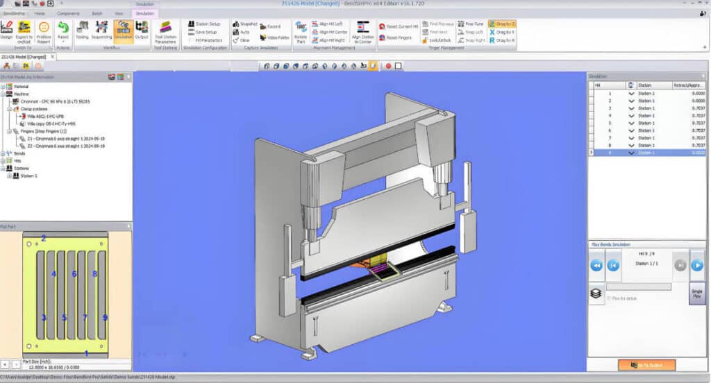
For complex parts, 3D simulation and collision detection technology, can be used to pre-check the bending sequence, flipping paths, and potential collision risks.
How Six Axes Work Together
Sensors, Compensation, and Software
Core Technologies of 6 axis Press Brakes: Y1/Y2, backgauge, crowning, and simulation
High-Precision Independent Y1/Y2 Control and Synchronization Accuracy
The Y1 and Y2 axes control the ram position and synchronization status of the ram’s left and right sides, respectively. This is the foundation for ensuring consistent bend angles.
When processing long workpieces, off-center loads, or situations with uneven left-right forces, stable Y1/Y2 axis synchronization effectively minimizes differences in bend angles between the left and right sides, thereby reducing rework and secondary corrections.
Multi-Station Capability Enabled by the multi-axis backgauge system
The X-axis handles the backgauge positioning, the R-axis adjusts the backgauge height, and the Z1/Z2 axes enable independent left-right movement, and multi-station configuration. These axes support multi-station bending with rapid position switching, and rapid tool change capabilities, significantly reducing processing time, and improving production efficiency.
At the same time, they enhance optimization performance for asymmetrical parts, double-bend sequences, and complex bending paths, thereby preventing human errors, and repetitive processes.
Automatic Crowning and Angle Closed-Loop Control
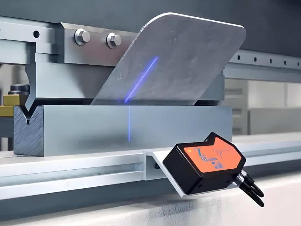
Automatic crowning is primarily used to address angle inconsistency, between the center and ends of a workpiece, during the bending of long parts, caused by deformation of the ram, worktable, and frame under load. Angle closed-loop control typically relies on an angle measurement system, and a CNC control system for angle correction, based on actual measured angles.
Although these two configurations can significantly improve consistency in batch production, not all 6 axis press brakes are equipped with them.
Quick Tool Change, Tooling Library, Program Library, and 3D Bending Simulation
Quick tool change can significantly improve production efficiency, while the tooling library and program library enable rapid data identification and execution. 3D bending simulation allows for inspection and optimization of the bending sequence during the offline stage, thereby reducing trial-and-error costs.
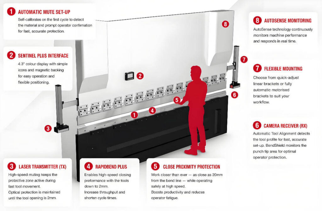
Safety Systems and Ergonomics (Light Curtains, Foot Switches, Two-Hand Controls)
Safety devices such as light curtains, foot switches, and two-hand controls effectively protect operators, prevent accidents, and ensure long-term, orderly production in the factory. Ergonomic design supports operators’ work, reduces worker fatigue, and improves operational consistency.
What Production Issues Can a 6 axis Press Brake Solve?
Precision and consistency
Cost Reduction
Improving Processing Efficiency and Automation Levels
6 axis press brakes feature a multi-axis coordinated control system, providing a foundation for automation. When equipped with automated loading/unloading systems and bending robots, production line efficiency for processing complex workpieces will significantly improve, and automation levels will rise accordingly.
Meeting Bending Requirements for Complex Workpieces
With an independent multi-axis control system and a highly flexible backgauge system, 6 axis press brakes can process complex parts with irregular shapes, asymmetry, and multiple bending sequences, meeting the diverse demands of modern sheet metal manufacturing.
4 Axis Press Brakes vs. 6 axis Press Brakes: What Is the Real Difference?
|
Comparison criteria |
4 axis CNC press brake |
6 axis CNC press brake |
|---|---|---|
|
Axis count definition by manufacturer |
Definitions vary by manufacturer; common configurations include Y1/Y2/X/R or X/R/Z1/Z2 |
Common configurations include Y1/Y2/X/R/Z1/Z2, or X1/X2/R1/R2/Z1/Z2 |
|
Backgauge positioning flexibility |
Capable of handling most standard bending operations |
Better suited for complex parts, asymmetrical parts, and multi-reference positioning |
|
Support for asymmetrical parts |
Requires manual positioning assistance or multiple rotations |
Independent Z1/Z2 positioning reduces the need for flipping and repositioning |
|
Support for deep flanged parts |
Susceptible to support height limitations |
Flexible coordination between the R-axis and Z-axis makes it suitable for complex deep-flange bending |
|
Multi-station switching |
More reliant on manual adjustments |
Multi-station automatic switching enables rapid changeover |
|
Consistency for long workpieces |
Depends on frame rigidity, tooling condition, and crowning systems |
Independent control of Y1/Y2, combined with a crowning system, ensures better consistency for long workpieces |
|
First-piece setup |
High efficiency for simple parts; frequent trial-and-error for complex parts |
Faster first-piece setup for complex parts, with precise parameter storage and recall |
|
Dependence on operators |
Moderate to high |
Lower operator dependence, suitable for stable multi-shift production |
|
Applicable scenarios |
Conventional symmetrical parts and shallow flanged parts; limited budget |
Asymmetric parts, deep-flanged parts, box-shaped parts, bent parts, high-precision parts, and high-mix low-volume production |
|
Investment cost |
Lower initial cost |
Higher initial cost, but long-term costs can be reduced by minimizing setup time and rework |
Compared to 4 axis press brake, 6-axis models reduce secondary positioning and first-piece trial-and-error adjustments, effectively reducing the need for subsequent corrections. With independent Y1/Y2 control and crowning technology, they significantly improve accuracy and consistency, while offering markedly greater flexibility.
Typical Applications of 6 axis Press Brakes
Automotive and Commercial Vehicles
In the automotive sector, 6 axis press brakes are primarily used to bend components for everyday vehicle use, including crash beam reinforcement plates, seat slide rail brackets, wiring harness mounting brackets, power battery box frames, and windshield wiper motor brackets. Using 6 axis press brakes improves the dimensional consistency, and assembly stability of these structural components.
Aerospace and Rail Transportation
Components in the aerospace sector, such as, aircraft interior fasteners, equipment brackets, electrical compartment door reinforcements, and inner frames for rail vehicle fairings, demand extremely high precision. 6 axis press brakes can reduce rework during the bending process, thereby increasing the precision and consistency of aerospace components.
Enclosures, Cabinets, and Electrical/Electronic Equipment
Equipment such as enclosures, cabinets, electrical cabinets, server racks, and control cabinets typically require multiple bends, short flanges, hole positioning references, and tight assembly tolerances. By utilizing multi-axis backgauge positioning, program calls, and controlled bending sequences, 6 axis press brakes can minimize errors caused by manual material positioning, thereby improving dimensional consistency for panels, door panels, mounting brackets, and enclosure structural components.
When Should You Choose a 6-axis CNC Press Brake?
Before selecting a 6 axis press brake, the question is not “Is a 6 axis press brake better than a four-axis one?”, but rather “Do your current workpieces and production methods truly require a 6 axis press brake with greater backgauge flexibility?”
The advantages of a 6 axis press brake become particularly evident when your workshop is already experiencing the issues listed in the table below:
|
Current issues at the factory |
What this indicates |
Upgrade directions |
|---|---|---|
|
Extended setup time for the first part of a complex part |
Operators need to repeatedly align the material, perform trial bends, and make adjustments |
6-axis CNC press brake |
|
Asymmetrical parts often require repositioning |
Insufficient flexibility of the backgauge |
Z1/Z2 or multi-axis backgauge |
|
Deep-flanged parts are prone to interference or unstable positioning |
The backgauge is limited by height and support methods |
R-axis stroke and backgauge structure |
|
Errors tend to accumulate in bent parts with multiple bends |
Incorrect bending sequence; unstable reference points and material alignment points |
Standardize bending sequences and upgrade 3D simulation capabilities |
|
Inconsistent results across multiple shifts |
Over-reliance on personal experience |
Program storage and recall capabilities, backgauge positioning capabilities, and crowning capabilities |
|
Frequent changeovers result in excessive machine setup time |
Insufficient program recall capability |
Tooling library, program library, and multi-axis coordinated control |
|
Angle inconsistency at the center and ends of long workpieces |
Incorrect crowning settings or uneven force distribution |
Crowning system |
|
Seeking to take on higher-precision complex-part orders |
Current configuration is unable to handle the current order type |
6-axis or 6+1-axis configuration |
When selecting a machine, we recommend verifying the following points:
Additionally, when purchasing a 6 axis press brake, it is essential to verify the travel ranges of the X, R, and Z1/Z2 axes. Ensure that the X-axis can accommodate the maximum flange dimensions of the workpiece, that the R-axis meets the positioning height requirements for deep flanging and multi-pass bending, and that the Z1/Z2 axes can accommodate various workpiece widths, and support multi-station positioning.
For complex workpieces, bending simulation software should also be used to check for potential collision risks, between the stop fingers, tooling, workpiece, and machine body.
If you are comparing 4 axis, 6 axis, or 6+1 axis press brakes, please provide us with your workpiece types, maximum bending length, material thickness, batch size, and changeover frequency. RAYMAX can offer reasonable axis configurations and configuration recommendations based on your actual operating conditions.
tonnage
When choosing tonnage, consider the material type, thickness, and maximum bending length of the workpieces to be processed. Generally, the tonnage should include a margin of safety beyond the maximum processing requirements; therefore, companies should prioritize calculations based on the most demanding operating conditions.
Axis Configuration and Options
Common 6-axis configurations for the entire machine include Y1/Y2, X, R, Z1, Z2. If you need to process long workpieces and have high requirements for angle consistency, consider adding a V-axis or an automatic crowning system; if you prioritize first-piece setup efficiency, and angle stability during batch production, consider equipping the machine with an angle measurement system or a closed-loop angle control system.
Additionally, if frequent changeovers or a wide variety of workpieces are required, you should consider equipping the machine with a quick-clamping system, a tooling library, a material database, and 3D simulation software.
Control Systems and Software
When selecting a 6 axis press brake, the control system must include these key functions: multi-axis coordinated control, graphical programming, bending sequence management, material database, tooling library, and collision detection.
For complex parts and production scenarios requiring frequent changeovers, it is recommended to consider 3D simulation software, and offline programming systems. These features allow for the simulation of bending sequences prior to formal production, reducing trial-and-error during the first part setup, and on-site machine adjustment time, thereby improving production efficiency.
A control system is not necessarily better simply, because it is more advanced; rather, it must align with the factory’s operational practices, programming capabilities, and the complexity of the workpieces. For factories that frequently process complex parts and require frequent changeovers, priority should be given to systems that support graphical programming, tooling libraries, material databases, bending sequence simulation, and collision detection.
Precision and Consistency Metrics
Crowning systems and angle measurement systems are key configurations for improving angle consistency in long workpieces and ensuring batch stability; they play a vital role in handling springback and angles with significant deviations.
Maintenance and After-Sales Service
High-quality products are the guarantee for reducing post-purchase repair frequency; before purchasing, it is essential to carefully consider the repair costs in the event of a failure. A clear after-sales response mechanism is equally important, as it determines whether customers can effectively get up to speed and resolve related issues quickly.
Budget and TCO
The budget includes equipment procurement, tooling maintenance, energy consumption, lubrication, labor costs, and more. It is essential to perform a detailed calculation and carefully consider these factors before purchasing. Companies can improve production efficiency and reduce unit and labor costs through process libraries and automation integration, thereby lowering the TCO. If you are still comparing tonnage, machine length, drive type, control system, tooling, safety features, and after-sales support, our press brake buyers guide can help you evaluate the full purchasing decision more systematically.
What Configurations Affect the Price of a 6 axis Press Brake?
Key Factors Affecting the Price of a 6 axis Press Brake
The main factors affecting the price of a 6 axis press brake include: tonnage, table length, drive method, control system, backgauge structure, crowning system, die clamping system, safety features, and automation interfaces.
6 axis press brakes come in many different models, and prices vary significantly between them. For example, there are substantial price differences, between small-tonnage electric models, large-tonnage hydraulic models, long-table models, and 6+1-axis configurations.
Therefore, when purchasing, one should not focus solely on, whether it is a 6-axis machine, but rather pay close attention to the machine’s actual configuration, including:
RAYMAX 6 axis Press Brake Stock Model Reference Prices
The price of a 6 axis press brake cannot be determined solely by the number of axes; it must take multiple factors into account, such as tonnage, table length, hydraulic or electric drive systems, control systems, crowning, angle measurement, tooling clamping, and automation interfaces. All these factors influence the final quotation.
Taking RAYMAX’s current inventory of 6 axis press brakes as an example, their reference prices range from approximately $30,000 to over $60,000:
|
Model examples |
Control axes |
Tonnage / Length |
Drive type |
Reference Price |
|---|---|---|---|---|
|
35 Ton × 4 ft electric press brake |
6 axis |
35 ton / 1250 mm |
Fully servo-electric |
$31,500 |
|
45 Ton × 5 ft electric press brake |
6+1 axis |
45 ton / 1600 mm |
Fully servo-electric |
$34,900 |
|
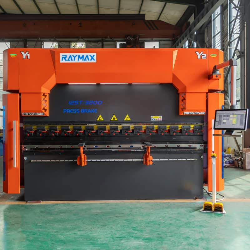
100 Ton × 10 ft CNC press brake |
6 axis |
100 ton / 3200 mm |
Hydraulic |
$30,000 |
|
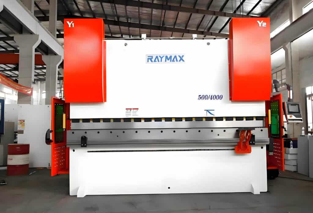
250 Ton × 13 ft CNC press brake |
6 axis |
250 ton / 4000 mm |
Hydraulic |
$45,000 |
|
300 Ton × 10 ft CNC press brake |
6 axis |
300 ton / 3200 mm |
Hydraulic |
$44,600 |
|
400 Ton × 13 ft CNC press brake |
6 axis |
400 ton / 4000 mm |
Hydraulic |
$63,300 |
As these stock quotes demonstrate, the price of a 6 axis press brake is not determined solely by tonnage; factors such as, drive type, table length, control system, stock availability, configuration options, and promotional pricing all influence the final price.
Therefore, when making a purchase, you should not focus solely on price ranges, but rather comprehensively compare key parameters, such as tonnage, length, axis configuration, control system, and core optional features.
The final quote should be based on a specific configuration list. If you need to process long workpieces, thick plates, deep-flanged parts, asymmetrical parts, or high-precision batch production, please provide the following information in advance: material, plate thickness, maximum bending length, tolerance requirements, and production volume. This will help us confirm the appropriate 6-axis or 6+1-axis configuration for you.
On-Demand Configuration and Phased Upgrade Strategy
The first phase involves confirming core 6-axis capabilities, including Y1/Y2 synchronization, X/R/Z1/Z2 travel, backgauge positioning, crowning, and basic program management capabilities.
In the second phase, angle measurement, offline programming, and 3D simulation are introduced based on precision requirements.
In the third phase, robotic bending, automatic loading/unloading, and production management system interfaces can be added according to production line needs, gradually forming an automated bending cell.
Conclusion
The core value of a 6 axis press brake does not lie in the number of axes, but in its ability to enhance positioning flexibility for complex workpieces, improve first-piece setup efficiency, and ensure batch reproducibility. For asymmetrical parts, deep-flanged parts, box-shaped parts, multi-pass continuous bent parts, and high-frequency changeover production scenarios, a 6-axis or 6+1-axis configuration can effectively reduce manual positioning errors, the need for secondary positioning, and repeated trial bends.
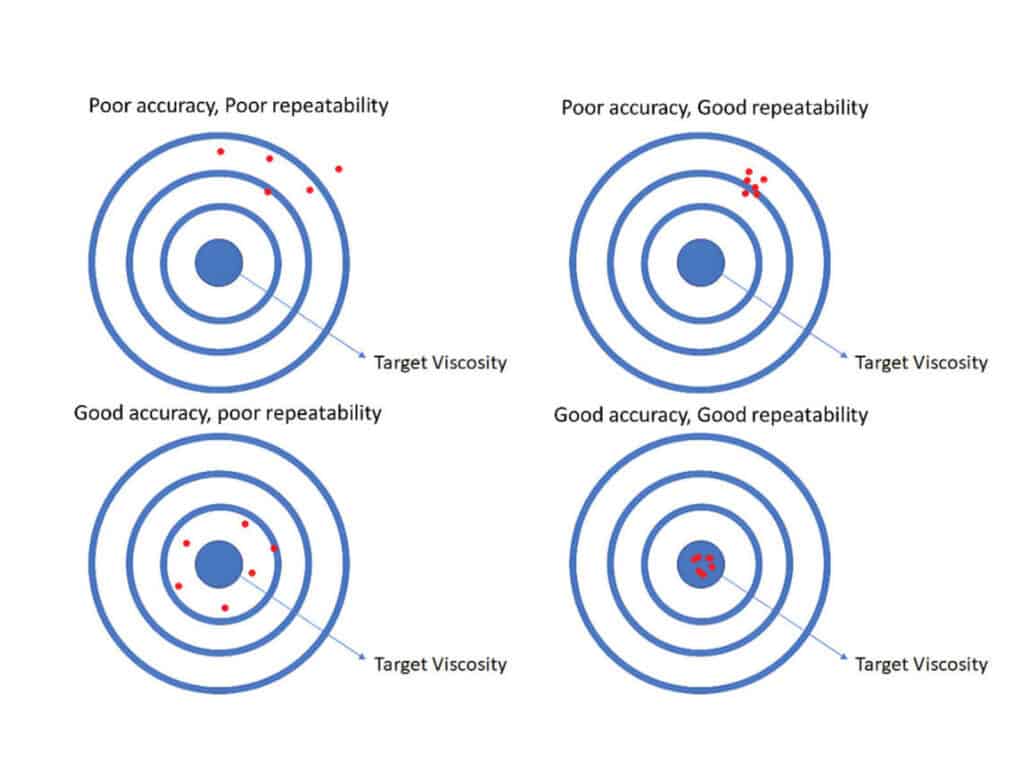
However, having six axes does not necessarily guarantee high precision; final accuracy is influenced by various factors, such as, frame rigidity, ram synchronization accuracy, backgauge repeatability, tooling condition, V-die opening selection, crowning, the control system, and the first part verification process.
When making a purchase, it is essential to comprehensively evaluate, whether a 6-axis configuration is truly necessary by considering requirements, such as workpiece drawings, material thickness, maximum bending length, tolerance requirements, and production pace.
If you are evaluating a 6 axis press brake, please feel free to send us details regarding your workpiece type, material, sheet thickness, bending length, and production volume requirements. RAYMAX will provide you with suitable configuration recommendations.
Frequently Asked Questions about 6 Axis Press Brakes
Related Blog
Press Brake Crowning Explained: Deflection, Angle Variation, Adjustment & System Comparison
Press Brake Software: Basics, Implementation, Examples & Selection Guide
Press Brake Bending Accuracy Checklist: 10 Quantified Factors to Inspect
How to Spec a Press Brake for Tolerance: Angle, Flange Length, Crowning, Backgauge & Acceptance Checklist
How to Improve Press Brake Bending Consistency: Causes, Checks & Solutions
Press Brake Repeatability vs Accuracy: Definitions, Test Methods & Common Misunderstandings
One Article to Master CNC Press Brakes: Types, Workflow, Structure & Buying Tips
Press Brake Guarding Systems & Requirements: OSHA & ANSI Safety Guide
What Is a 3 Axis Press Brake? Complete Guide to Structure, Benefits & Selection
NC vs CNC Press Brake: Key Differences, Selection Guide, and Industry Applications
What is a Press Brake Back Gauge? Types and Key Components Explained!
What is an 8 axis press brake: Why It’s the best investment for complex bends
Post Your Review
Share Your Thoughts And Feelings With Others
One response to “What is a 6 Axis Press Brake? Working Principles, Advantages, Applications, and Buying Guide”
I appreciate you sharing this blog post. Thanks Again. Cool.