Francis Pan is the Foreign Trade Manager of RAYMAX, with over 10 years of experience in sheet metal fabrication equipment and CNC machinery. He has worked closely with manufacturers worldwide on press brakes, fiber laser cutting machines, fiber laser welding machines, and practical production-oriented metal processing solutions.
Press brake tooling may seem simple—just an upper punch and a lower die—but it plays a critical role in bending.
Many beginners assume that once the tooling is installed, bending can begin, but in reality, the outcome depends on much more than that. What really matters is whether the tooling interface is compatible, whether the geometric shapes match the workpiece, whether the lower die opening is appropriate, whether clearance has been properly accounted for, and whether the tooling is suitable for the current bending process. Choosing the wrong tooling can lead to issues such as poor angle accuracy, indentations on the sheet surface, failure to form short flanges, and tooling wear.
Therefore, to truly understand press brake tooling, the most important thing is not to memorize the names of various tooling types, but to learn how to evaluate and select them based on interfaces, geometry, process requirements, material, and sheet thickness.
30-second quick reference chart
Your top concerns right now
Which section to review first
What tooling can my machine accommodate?
Tooling interfaces and compatibility systems
Which upper punch should I choose?
Upper punch types and clearance logic
What V-opening should I choose for the lower die?
Lower die types and key parameters
Why can’t I bend short flanges, or why do box parts collide with the tooling?
Minimum flange dimensions and interference analysis
Why are there indentations or scratches?
Non-marking tooling and surface-sensitive part solutions
Why is the angle inconsistent?
Bending methods, V-openings, springback, and machine factors
How can I avoid making mistakes when purchasing tooling?
Selection process and procurement list
Who should read this article
Purchasing personnel: Need to understand interface compatibility to avoid tooling selection errors;
Process engineers: Need to select appropriate bending process solutions based on the material and type of workpiece;
Shop floor supervisors: Need to improve tooling changeover efficiency and reduce tooling wear;
Novice press brake operators: Need to quickly interpret drawings and know which tooling to select for specific sheet thicknesses and shapes.
What is press brake tooling, and what is its relationship to the press brake itself?
What is press brake tooling?
Press brake tooling typically refers to the upper punch, the lower die, and related tooling components, which work together to bend and form the workpiece. Press brake tooling is not merely an accessory on the press brake; rather, it is a critical component involved in the bending and forming process. It is the primary factor determining the final shape of the workpiece, whether short-edge bending is possible, whether the workpiece surface can be protected, and whether collisions between the workpiece and the tooling, equipment, or other bending edges can be avoided.
Why you can’t just “pick any tooling”
Many beginners assume that as long as the machine has sufficient tonnage, they can simply choose any set of tooling to complete the bending task. This is a common misconception on the shop floor. Having sufficient machine tonnage does not mean you can choose tooling arbitrarily; just because the first piece bends to the correct angle does not guarantee stable batch production.
If the wrong tooling is selected, problems such as the following may occur:
An incorrect punch tip radius will affect the quality of the bend line, forming stability, and tooling wear control.
It is important to note that in air bending, the final inside radius of the workpiece is typically not directly “formed” by the upper punch’s tip radius, but rather results from a natural inside radius created by the material, the bending angle, and the lower die’s V-opening;
Insufficient minimum flange length and inadequate support can cause the workpiece to slip directly into the lower die, resulting in failure to form;
When bending the final few edges of deep box parts, collisions may occur with the punch;
The surface of stainless steel or aluminum sheets may be indented;
When bending thick plates, insufficient load-bearing capacity of the tooling may cause it to crack, shortening its service life;
Incompatibility between the tooling and the clamping system may prevent the tooling from being installed or cause instability once installed, resulting in reduced bending accuracy.
What tooling determines and what it does not
To ensure bending quality, we must first understand which outcomes are directly determined by the tooling and which cannot be determined by the tooling alone.
Direct influences of the tooling:
The geometric shape of the workpiece, clearance capacity, whether it will collide with the equipment or other bending edges, the conditions of the V-die opening, the minimum flange length that can be bent, whether the workpiece surface will be indented, whether the workpiece surface can be protected, and tool change efficiency.
Factors not determined solely by the tooling:
The angular accuracy of the final workpiece shape, batch consistency, angular consistency along the entire length, and springback control results.
This is because these factors are influenced not only by the tooling but also by material variations, machine rigidity, the repeatability of the backgauge positioning, crowning capability, and programming and operating methods.
Press Brake Upper Tool – Punch Assembly Diagram
How should press brake tooling be classified?
There are many types of press brake tooling. Many articles tend to mix up tooling interfaces and compatibility systems, the geometric shapes of upper punch and lower dies, and their actual process applications, leaving readers still unclear about the different types of press brake tooling after reading.
What are the common points of confusion?
Treating different interface systems such as “American, European, WILA, and TRUMPF” as being on the same level;
Mixing discussions of punch and lower die geometries—such as “gooseneck punches, acute-angle punches, and V-dies”—with interface systems like “American, European, WILA, and TRUMPF”;
Discussing punch and lower die geometries (such as “gooseneck punches, acute-angle punches, and V-dies”) alongside process applications (such as “air bending, flattening, and Z-bending”);
Including clamping systems, backgauges, and compensation systems within the tooling classification discussion.
Why this classification method misleads readers
The classification methods described above may lead readers to believe that there is only one way to categorize tooling types, which could cause them to confuse interface and geometric issues during procurement. For example, if we purchase a set of European-style gooseneck tooling but find upon arrival at the workshop that they cannot be installed, this is due to an incorrect interface.
Another potential issue with this classification method is that while the tooling may fit on-site, the workpiece cannot be formed. In this scenario, the interfaces are compatible, but the geometric shapes or the lower die openings do not align.
Some articles appear to cover a lot of ground, but in reality, they do not truly tell readers how to make judgments when reviewing drawings.
What classification framework will be used in the rest of this article
To help readers organize their thoughts effectively, the remainder of this article will be structured around the following three levels:
Level 1: Classification based on tooling interfaces and compatibility systems, aimed at determining whether the tooling can be installed stably;
Level 2: Classification based on the geometry and structure of the upper punch and lower dies, aimed at determining whether the target shape can be formed;
Level 3: Classification based on specific process purposes and application scenarios, aimed at determining which bending method to use.
Classification by tooling interfaces and compatibility systems
If you are new to press brake tooling, you can start by understanding these tooling categories in simple terms:
American-style tooling tends to be more traditional and versatile, European-style tooling is more commonly used in modern CNC machines, WILA-system tooling is geared toward high-precision quick-change systems, and TRUMPF-style tooling is designed to integrate with the brand’s ecosystem.
While this approach may not be textbook-perfect, it is better suited for procurement professionals, novice operators, and entry-level process engineers to quickly establish a framework for making informed decisions.
American-style tooling
Characteristics: A traditional, general-purpose tooling system that is widely available on the market, easy to procure, and relatively cost-effective.
Applications: Commonly used with traditional manual clamping or older-model press brakes, or in workshops that primarily rely on universal stock tooling.
Advantages: Highly versatile; procurement and replacement costs are typically low, resulting in relatively low overall costs.
Disadvantages: Relatively low repeatability; efficiency is lower in applications requiring frequent tool changes.
European-style tooling
Characteristics: A tooling style commonly used with modern CNC machines, typically better suited for segmented tooling and quick tool changes.
Applications: Commonly found on modern CNC press brakes; suitable for production scenarios involving multiple product varieties, small batches, and frequent changeovers.
Advantages: Easier to integrate with precision clamping systems and segmented tooling, improving tool change efficiency and repeatability.
Disadvantages: Relatively higher cost compared to American-style tooling; compatibility issues may arise between different manufacturers.
WILA system tooling / WILA-compatible tooling
Features: High-precision quick-change tooling that places greater emphasis on accuracy, tool change efficiency, and systematic compatibility.
Applications: Suitable for workshops with higher requirements for precision, tool change speed, and automation.
Advantages: Higher repeatability and clamping consistency, faster tool change speeds, and greater compatibility; better suited for high-precision workpieces and scenarios requiring frequent tool changes.
Disadvantages: High procurement costs; even compatible tooling cannot simply be equated with the actual performance of the original system.
TRUMPF-style tooling / TRUMPF-compatible tooling
Features: Brand-ecosystem-integrated tooling that emphasizes use as a complete set with corresponding equipment and systems.
Applications: Designed specifically for TRUMPF and compatible machine models.
Advantages: Typically offers better compatibility with corresponding equipment, high repeatability, fast tool change speeds, and significant advantages in system integration.
Disadvantages: High procurement costs; model compatibility, system matching, and future expandability must be specifically verified.
Comparison table of tooling interfaces and compatibility systems
Categories
Applications
Advantages
Important notes
Best suited for which types of factories
American-style tooling
Traditional press brakes
High versatility and low cost
Do not rely solely on appearance; always verify that the tang is compatible with the clamping mechanism.
Those with low tool change frequency requirements and a limited budget
High segment accuracy, precise clamping, and fast tool change
Compatibility may still vary between different manufacturers.
Those producing a wide variety of products in small batches with frequent tool changes
WILA-style tooling
High-precision bending, quick tool changes, and automation upgrades
High precision, fastest tool change, and high level of automation
The original system and the compatible solution are not necessarily equivalent.
Those with high precision requirements and plans to implement automation in the future
TRUMPF-style tooling
Systems designed specifically for TRUMPF machines or compatible systems
Comprehensive support, safe tool change, and stronger system integration
When purchasing, carefully verify model compatibility and system compatibility
Those who have already purchased or are planning to purchase TRUMPF machines
What should you really focus on when it comes to the interface system?
Before purchasing tooling, you should confirm the following key factors:
What type of clamping system does your existing machine use?
Is the shank design compatible with your existing interface?
Does it support quick tool change?
What is the clamping method? Is it manual mechanical clamping, pneumatic clamping, or hydraulic clamping?
Are you planning to upgrade to an automatic tool change system in the future?
Do you need to purchase segmented tooling?
If you are requesting a new machine or tooling package, include the tooling brand, interface standard, clamping method, tool height, and segmented tooling needs in your press brake RFQ template before comparing supplier quotes.
Common mistakes in this area
Mistake 1: Focusing only on the tooling’s appearance and ignoring the interface type.
Consequence: You discover after purchasing the tooling that it won’t fit, or that it is unstable once installed.
Correct approach: Before purchasing, verify the specifications of the tooling’s shank to ensure it matches your existing interface.
Mistake 2: Focusing only on the brand and ignoring compatibility specifications.
Consequence: You buy tooling from a major international brand, only to find it is incompatible with your domestic equipment.
Correct approach: When purchasing, do not focus solely on the brand’s reputation; instead, verify that the tooling is compatible with your equipment.
Mistake 3: Assuming that if tooling fits, it will necessarily function stably.
Consequence: Unstable positioning during bending, resulting in poor bending accuracy.
Correct approach: After installing the tooling, use a dial indicator to measure its levelness and check whether it is securely clamped. After clamping, inspect the alignment, stability, and repeatability of positioning; specific tolerances should follow the standards of the equipment and tooling system.
Mistake 4: Ignoring the impact of clamping methods on accuracy and tool change efficiency.
Consequences: After prolonged use, screws may loosen, accuracy errors may increase, and tool change speeds may slow down.
Correct approach: Select an appropriate clamping method based on the factory’s tool change frequency and accuracy requirements.
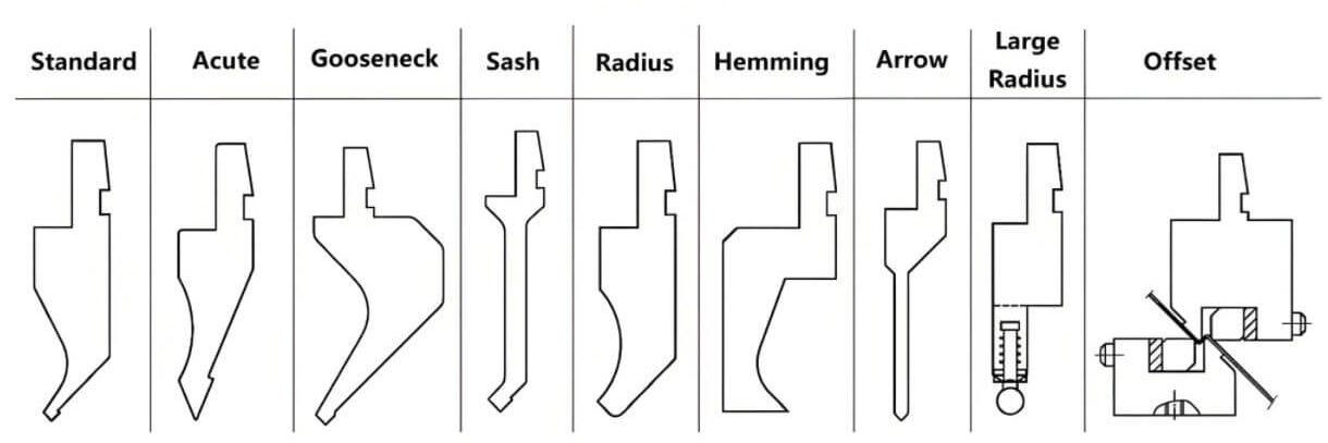
Press brake punch (Classification by Upper Punch Geometry and Application)
General punch type collection
Straight-Body and General-Purpose Punches
Standard punch
1. Standard punches
Features: Neat and regular shape; the body is typically straight-body in structure; the tip features a common pointed-tip design; no distinct clearance contour is provided.
Applications: Suitable for most routine bending operations, such as ordinary straight edges, standard-length flanges, and common contoured parts; it is the most commonly used basic punch in many factories.
Common tip angles: Typically 88°, 85°, 86°, and other standard angles, depending on the manufacturer’s series and process requirements.
Acute-angle punch
2. Acute-angle punch
Features: Similar in appearance to standard punches, with an overall straight-body structure, but the tip is sharper than that of a standard punch, making it suitable for smaller angles or specific forming requirements.
Applications: Typically used for small-angle bending or as a foundation for forming high-springback materials. A “sharper” tip does not necessarily mean greater precision during bending; rather, it better meets specific bending process conditions.
Common tip angles: Typically include acute-angle series such as 30°, 28°, or 26°, with similar variations available from different manufacturers.
Standard Punch vs. Acute-Angle Punch:
Similarities: Both are straight-body universal punches;
Differences: The distinction lies in their tip angles and applicable processes, not in whether they provide clearance.
Note:
If the primary focus on-site is on small-angle forming, springback compensation, or tip angle matching, you should first distinguish between standard punches and acute-angle punches;
If the primary concern is whether interference with the workpiece sidewall or existing bends is likely to occur, you should continue to review the narrow-body punches and clearance punches below.
Narrow-Body and Transition-Type Punches
Narrow punch
1. Narrow punch / Sword-shaped punch
Features: The blade is narrower and slimmer, with an overall sword-like shape. Compared to standard punches, it can more easily reach into narrow spaces, providing greater access and clearance for the workpiece; however, it is not, by nature, a typical large clearance punch.
Applications: Commonly used for operations near short edges, deep cavities, in confined spaces, or near pre-bent edges. However, due to its overall thin profile, its load-bearing capacity must be strictly verified to prevent breakage caused by excessive loads.
Angle Notes: The core distinction of this punch type lies in its narrower body and easier access to spaces, rather than a fixed tip angle; In practice, it can be manufactured with standard angles such as 88° or 85°, or configured with smaller angles.
Note:
Some narrow punches also feature more balanced or symmetrical side profiles, allowing better access than standard punches while still offering less clearance than a true gooseneck punch.
In some tooling catalogs, certain very narrow punches with angled tips may also be referred to as sash punches, especially for door sash or jamb-related applications.
Narrow-body punches, sword-shaped punches, and symmetrical narrow-body punches can be understood as “narrow-body, semi-clearance, transitional punches.” Compared to standard punches, these three types are easier to insert into tight spaces, but their clearance capability is generally still weaker than that of true gooseneck punches or deep-contour punches.
Narrow-Type/Symmetrical Narrow-Body Punches: Thinner body, easier to insert;
Gooseneck/Deep-Profile Punches: Feature a distinct recess, designed specifically for clearance.
Clearance and Complex-Profile Punches
Gooseneck punch
1. Gooseneck punch
Features: The upper section is very narrow, while the lower section features a distinct recessed design, forming a shape resembling a “goose neck” and offering strong clearance capability. Some goose-neck punches incorporate greater throat depth and deeper groove contours to accommodate deeper boxes, taller side walls, and more complex multi-bend parts.
Applications: Ideal for box-shaped parts, return bends, complex-contour parts, and workpieces with existing side walls, significantly reducing the risk of interference between the workpiece and the punch. For deep-box bending operations with higher clearance requirements, deepened or large-throat-depth gooseneck punches can also be selected.
Angle Notes: The key to gooseneck punches lies in their clearance recesses and throat depth structure, rather than a fixed tip angle; In practical applications, different tip angles can be configured based on the process requirements.
Special forming punches
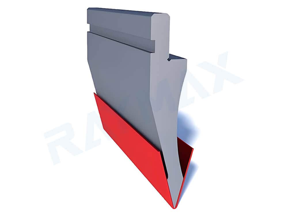
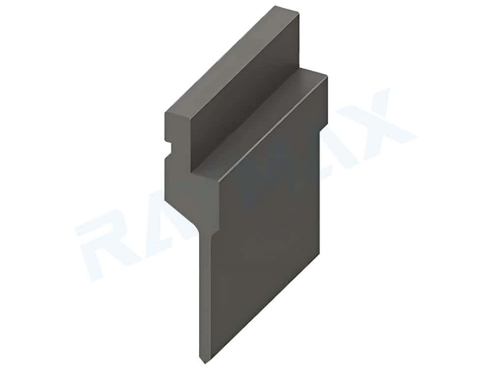
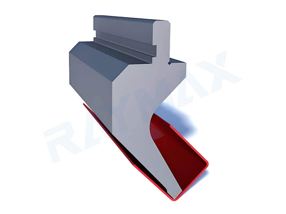
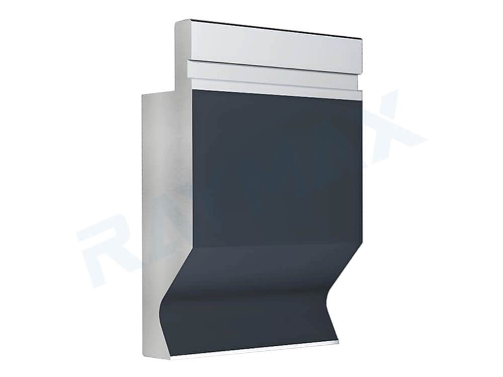
Offset Punch( Z-Bend Punch)
1. Offset punch / Z-bend punch
Features: Its profile is not a single sharp point, but rather a contour with a distinct stepped or offset appearance.
Applications: Typically used in conjunction with a matching offset die to form two adjacent, opposite bends in a single operation; suitable for certain Z-shaped structures and stepped parts.
Flattening Punch
2. Flattening punch
Features: The working edge is not a conventional sharp point but rather a shape resembling a flat surface or wide contact area.
Applications: Typically used as a second step after bending, primarily to flatten and compact the workpiece’s edges, resulting in a smoother appearance.
Hemming Punch
3. Hemming punch
Features: The working surface is typically not a conventional sharp point, but a specialized structure designed to curl, fold, or wrap the edge.
Applications: Typically used to curl or fold the edges of workpieces, not only improving the aesthetic appearance but also preventing safety hazards caused by excessively sharp edges that could cut hands. Commonly used for exterior parts or safety-edge components.
Radius Punch
4. Radius Punch / Large-Radius Punch
Features: The tip of the punch is not a sharp point, but a large arc shape.
Applications: Primarily used for forming large internal fillet radii, suitable for certain aluminum parts prone to cracking, thick plates, or special cosmetic components.
Rotating Punch
5. Rotating punch
Features: This is a more advanced and specialized type of punch. The working part of this punch can rotate, rather than having a standard fixed cutting edge.
Applications: It effectively reduces material drag and is specifically used for bending parts with special surface requirements or complex contours.
window punch
6. Window punch
Features: The body of the punch features a distinct clearance area in the center, allowing the workpiece to pass through the opening in the punch body.
Applications: Suitable for deep, narrow channels, deep box parts, or special contour parts that require passing through the center of the punch body.
Angle Notes: The core feature of this type of punch is the central window structure, rather than a fixed tip angle.
Advanced and custom upper punches
Heavy-duty punches
1. Heavy-duty punches
Features: A thicker body, offering greater strength, rigidity, and load-bearing capacity.
Applications: Suitable for heavy-duty conditions such as thick plates, high tonnage, heavy loads, and high-strength steel.
Features: Equipped with internal sensors that integrate with high-end CNC systems to measure and compensate for angles during the bending process.
Applications: Suitable for highly automated operations with stringent precision requirements.
4. Custom punches / Special-profile punches
Features: The profiles of these punches are often specifically designed for special parts in certain industries.
Applications: Suitable for complex, irregularly shaped parts and specialized components in the aerospace, automotive, home appliance, and structural component sectors.
Comparison table of common upper punch applications:
Upper Die Types
Typical Applications
Key Features
Common Limitations
Suitable for clearance applications?
Standard Punch
Conventional air bending, standard workpieces
High versatility, low cost, and excellent strength
Poor clearance capability; not suitable for complex interference conditions
No
Acute-Angle Punch
Small-angle forming, materials with high springback
Sharper tip, better suited for bending at specific angles
Sharp punches are prone to scratching softer materials; poor clearance capability
No
Narrow/Sword-Shaped Punch
Short edges, confined spaces
Narrower design for easier access to tight spaces
Low load-bearing capacity; not a high-clearance punch
Limited
Symmetrical Narrow-Body Punch
Box-shaped parts, deep-cavity parts, hemmed parts
Superior access and maneuverability
Clearance capability is inferior to that of gooseneck punches
Moderate
Gooseneck Punch
Box-shaped parts, return bends, complex-contour parts
Excellent clearance capability
Relatively low load-bearing capacity
Yes
Window Punch
Deep, narrow channels, special-profile passages
The middle section of the punch body allows the workpiece to pass through
More specialized application range
Yes
Large-Radius Punch
Aluminum sheets, thick plates, exterior parts
Prevents cracking and ensures a smooth surface
Cannot bend workpieces with small inner radii
No
Z-Fold Punch
Z-shaped structural parts, stepped parts
Forms two adjacent opposite bends in a single pass
Suitable only for specific shapes
No
What should readers focus on when considering upper punches?
Simply memorizing the names of punches is meaningless; what matters is understanding the problems they actually solve. Therefore, when selecting a punch, keep this sequence in mind:
First, determine whether the workpiece and the punch will collide during bending and whether clearance is required;
Second, assess whether the workpiece has any special forming requirements;
Finally, verify that the punch’s tip radius, strength, and height meet the bending requirements.
Press brake die (Classification of lower dies by geometry and function)
Collection of die types
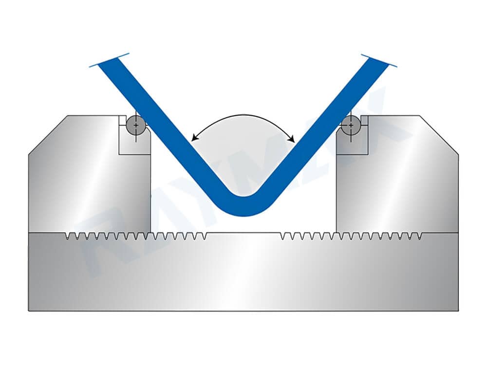
Conventional V-type lower dies
1V-die
1. Single V-type lower die
Features: The most common basic type of lower die, featuring a simple structure with a single V-die.
Applications: Suitable for basic bending operations in most factories. For air bending of low-carbon steel, the V-opening is typically set at 6T–8T as a rule of thumb; for bottoming of low-carbon steel, 8T is commonly used as a starting point; for high-strength steel, thick plates, or parts with high surface finish requirements, the V-opening often needs to be enlarged further. These empirical values should only serve as a starting point and cannot replace trial test bending.
2V-die
2. Double-V die
Features: Typically features two V-openings of different sizes; simply flipping the die allows for quick switching to the other set of V-openings.
Applications: Suitable for bending workpieces with adjacent thicknesses or for two sets of common operating conditions, effectively reducing tool change frequency.
3V-4V-die
3. Two-Way Self-Centering V-Die / Self-Centering 2V Die
Features: Similar in appearance to a standard double-V die, it also features two sets of V-openings. However, it optimizes the positioning method based on the standard double-V die, eliminating the need for recalibration after flipping.
Applications: It offers higher positioning accuracy and is suitable for scenarios involving frequent tool changes where recalibration is not required after switching.
Multi-V-die
4. Multi-V-type lower die
Features: A single lower die body features multiple V-openings of different sizes, allowing for flexible switching between workpieces with varying sheet thicknesses and angle requirements.
Applications: Ideal for production involving variable sheet thicknesses and small-batch, high-variety runs. Note: As the number of slots on the lower die body increases, the strength of each individual slot decreases; therefore, it is not suitable for very thick sheets.
5. Four-sided multi-V die / 4-way die
Features: Each of its four sides features a V-opening of a different size. Switching is achieved by flipping the lower die, offering greater flexibility and higher efficiency than single-V or double-V dies.
Applications: Suitable for scenarios involving frequent specification changes, small to medium batch sizes, and high-variety production.
Functional lower dies
U-shaped lower dies
1. U-shaped lower dies
Features: The slot is U-shaped rather than the typical V-shape, and is commonly used to form C-shaped or U-shaped structures.
Applications: Suitable for bending channel sections, channel-shaped parts, and certain U-shaped structural components.
Radius lower dies (Large-radius lower dies)
2. Radius lower dies (Large-radius lower dies)
Features: The slot is not a sharp V-shape but features a distinct curved transition, giving it a rounder appearance.
Applications: Typically used for forming larger fillet radii; generally requires a large-radius punch or special radius processes to achieve the final internal fillet.
Adjustable lower die
3. Adjustable lower die
Features: Typically incorporates an adjustable mechanism that allows the V-opening width to be flexibly adjusted according to different forming requirements.
Applications: It covers a wide range of widths and is ideal for bending workpieces of various specifications.
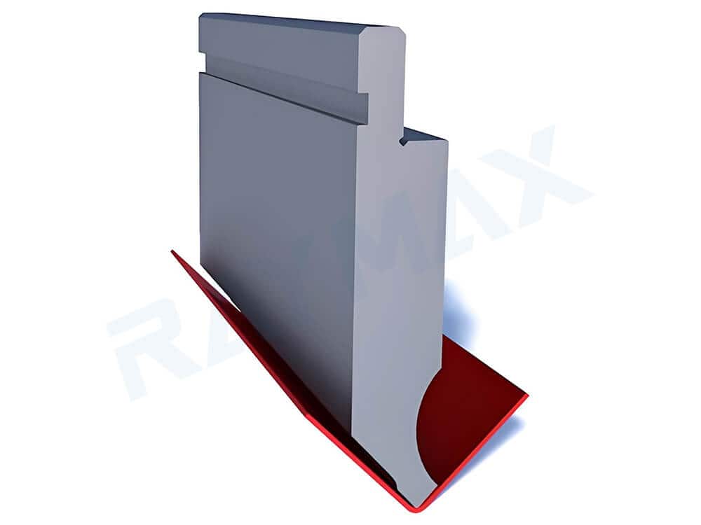
Special forming lower dies
Z-bending-or-step-bending-set
1. Offset lower die / Z-bending lower die
Features: The groove is not a standard V-shape but rather a step-like structure that allows the workpiece to be bent into a Z-shape in a single operation.
Applications: Typically used in conjunction with an offset punch for Z-shaped parts, stepped parts, and workpieces requiring two adjacent opposite bends to be formed in a single operation.
Flattening lower die
2. Flattening lower die
Features: Generally lacks a V-die structure, instead resembling a flat surface or a wide contact surface.
Applications: Typically used in the second step of the bending process, specifically to compact and flatten the workpiece’s edges, resulting in a more aesthetically pleasing and smoother finish.
Hemming die
3. Hemming die
Features: Its contour is not a standard V-shape but is designed to continue folding, hemming, or wrapping around the edge, functioning more as an edge-forming structure.
Application: Typically used in conjunction with a hemming punch for hemming and edge-folding operations. This not only enhances the strength of the workpiece edges but also improves the workpiece’s aesthetic appearance.
4. Insertable lower die
Features: This is a modular component that can be inserted into a corresponding lower die holder. When switching between workpieces of different specifications, there is no need to replace the entire lower die; only the inserted module needs to be swapped out.
Applications: Ideal for scenarios involving frequent die changes where replacing the entire lower die is undesirable. It offers high convenience and effectively reduces tooling changeover time.
5. Lower die base / Insertion-type lower die holder
Features: Serves as the base for insertion-type lower dies, used to install and secure them. It can remain permanently mounted on the machine.
Application: Used in conjunction with insertable lower dies; a single base can accommodate multiple sizes of insertable lower dies.
Surface protection and special material lower dies
Non-marking lower dies
1. Non-marking lower dies
Features: The working contact area typically incorporates designs to reduce direct metal-to-metal friction, such as large V-die edge radii, non-metallic contact layers, rolling contact, or anti-adhesion surfaces.
Applications: Ideal for bending surface-sensitive parts such as stainless steel, brushed sheets, mirror-finished sheets, and laminated sheets, as they minimize surface indentations and damage to the workpiece.
Polyurethane lower dies
2. Polyurethane lower dies / Polyurethane inserts
Features: A layer of polyurethane padding is embedded in the V-die opening contact area.
Applications: Allows the workpiece to contact the soft padding directly rather than hard metal, protecting the workpiece surface from indentation and making it suitable for bending parts with high aesthetic requirements.
Roller-type lower die
3. Roller-type lower die / Low-friction lower die
Features: Rollers are mounted along the edges of the V-die opening.
Applications: This design allows the workpiece to enter the lower die by rolling rather than sliding during the bending process, reducing friction between the workpiece and the lower die. It is suitable for bending workpieces with high surface finish requirements.
4. Coated lower die / Anti-adhesion lower die
Features: The contact surface of V-die opening is coated with an anti-adhesion coating.
Applications: Materials such as aluminum and galvanized sheet tend to adhere to the lower die during bending, causing surface damage. The coated lower die reduces material adhesion and surface damage by preventing direct contact between the material’s surface and the metal surface of the lower die.
Heavy-duty and custom lower dies
1. Heavy-duty lower dies
Features: Larger in size and made of higher-strength materials, offering superior load-bearing capacity and long-term stability.
Applications: Suitable for thick plates, high-tonnage, high-load, and high-strength steel applications.
2. Custom lower dies
Features: Specifically designed for special parts and components with complex contours.
Applications: Certain workpieces have unique bending profiles that standard lower dies cannot accommodate, necessitating custom lower dies. This is a common solution for complex workpieces.
3. Special-profile lower dies
Features: Designed specifically for particular industries and parts with unique cross-sections.
Applications: Suitable for specific industries, parts with unique cross-sections, and specialized profiles, such as certain automotive components, optical devices, structural parts, or parts requiring a specific appearance.
4. Specialized dies for corrugated/wavy forming
Features: The working profile typically features distinct corrugations or continuous undulating structures.
Applications: Specifically designed to form corrugated workpieces, such as container side panels, roofs, and other wavy cross-sections.
Comparison table of common lower die applications:
Lower die types
Suitable applications
Advantages
Risk factors
Suitable for surface-sensitive parts
Single V-die
Conventional air bending
Lowest cost, suitable for standard applications
Difficult to change die
Generally
Double V-die
Mixed production of two sheet thicknesses
Reduces tool change frequency
Slightly lower strength
Generally
Self-centering Double V-die
Frequent tool changes and scenarios requiring higher positioning efficiency
High positioning accuracy and fast tool change speed
Load-bearing capacity is lower than that of a single-V lower die, which may cause interference
Generally
Multi-V-die
Multiple product varieties and sheet thicknesses
Offers multiple V-dies for high flexibility
Heavier and wider die body
Generally
Four-sided multi-V-die
Frequent changeovers and multi-variety production
High utilization rate
Excessively large volume
Generally
U-die
Channel parts, channel-shaped parts, and special-contour parts
Capable of forming C-shaped or U-shaped structures
Narrow range of applications
Depends on the structure
Radius lower die / Large radius lower die
Forming large fillets
Works with rounded punches to create large internal fillets
Springback is more complex; standard air bending empirical values cannot be applied
Generally
Adjustable lower die
Variable operating conditions and flexible production
Covers a wide range of widths
Higher requirements for precision and repeatability during adjustment
Generally
Offset lower die / Z-fold lower die
Z-bends, stepped parts
When used with offset punches, can complete Z-shaped bends in a single operation
Narrower range of applications
No
Non-marking lower die
Surface-finished parts such as mirror-polished, brushed, and laminated sheets
Reduces indentations and surface damage
High cost; surface maintenance required
Yes
Flattening lower die
Hemming and edge clamping
Enhances workpiece edge strength and improves aesthetics
Requires use with a flattening punch; high process requirements
No
Hemming die
Hemming and edge-folding
Suitable for safety edges and aesthetic edges
Requires use with a hemming punch; high process requirements
No
Insert lower die / Die base system
Frequent changeovers
Flexible combinations and fast tooling changeover
Higher system complexity
Depends on the insert
Polyurethane lower die / Polyurethane inserts
Workpieces with high surface finish requirements
Reduces indentations and scratches through soft contact
Wear occurs with long-term use
Yes
Roller-type lower die / Low-friction lower die
Parts with high surface finish requirements and materials prone to surface damage
Reduces friction and drag marks through rolling contact
More complex structure; higher maintenance requirements
Yes
Coated lower die / Anti-adhesive lower die
Materials prone to sticking, such as galvanized steel, aluminum, and stainless steel
Minimizes surface damage
Requires regular cleaning and maintenance
Yes
Heavy-duty lower die
Thick sheets, high-strength steel, and high-tonnage applications
High strength and long service life
High cost; heavy die
Generally
Custom lower die / Special-profile lower die
Special industry parts and parts with unique cross-sections
Capable of bending special shapes
Narrow range of applications
Depends on the design
Why the lower die often has a greater impact on on-site results than the upper punch
This is because the V-die opening directly affects the force required for bending, the natural inside radius, the minimum flange length, the risk of indentations on the workpiece surface, the unfolded dimensions, and springback behavior.
In many on-site cases, the primary cause of bending failures is often not the upper punch, but rather the incorrect selection of V-die opening dimensions, groove shape, and process parameters.
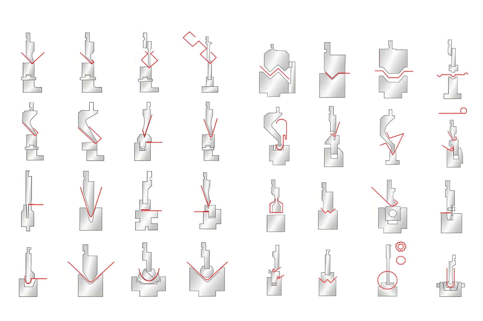
Classification by process purpose and application scenarios
Having previously examined press brake tooling from the perspectives of interface systems, upper punch geometry, and lower die geometry, we will now learn how to match tooling with actual bending tasks in real-world process scenarios.
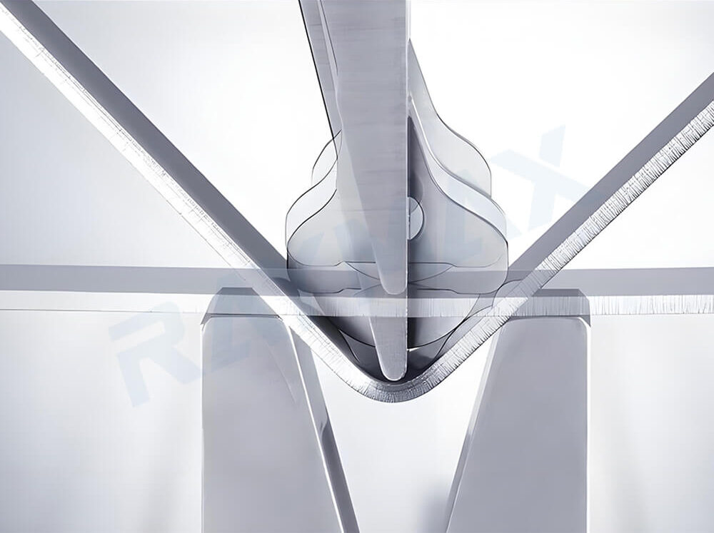
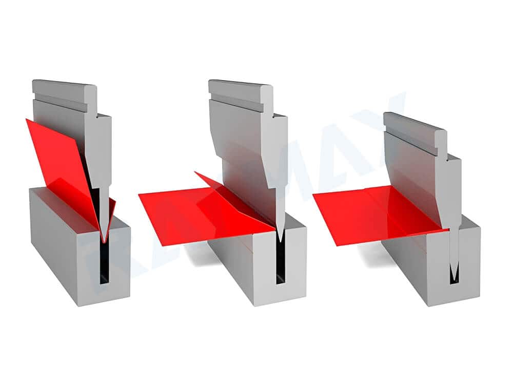
Tooling for conventional air bending
Common tooling combinations: Standard punch paired with a conventional V-die.
Suitable applications: Suitable for most basic bending operations; this is the most common starting tooling combination. The advantage of air bending is its high flexibility; a single set of basic tooling can often cover a wide range of angles and many standard workpieces.
Tooling for bottoming
Common tooling combination: A punch with the corresponding angle paired with a V-die with the corresponding angle.
Suitable applications: Suitable for operations requiring higher precision in angle control and forming strength. Bottoming demands stricter tooling matching and requires higher tonnage than air bending, making it more suitable for scenarios with higher precision requirements and where tooling and workpieces are more stable.
Tooling for coining
Common tooling combinations: Specialized high-strength punch paired with a specialized high-strength die.
Suitable applications: Ideal for operations requiring extremely high forming pressure and seeking to minimize springback as much as possible. Coining requires immense pressure and places very high demands on press tonnage and tooling load-bearing capacity; generally, coining is more suited to specific process requirements.
Tooling for Z-bends / Offset bends
Common tooling combinations: Offset punch paired with an offset die.
Suitable applications: Specifically designed for bending stepped parts and Z-shaped structures. Its greatest advantage is the ability to form two adjacent opposite bends in a single operation, offering higher efficiency than conventional bending.
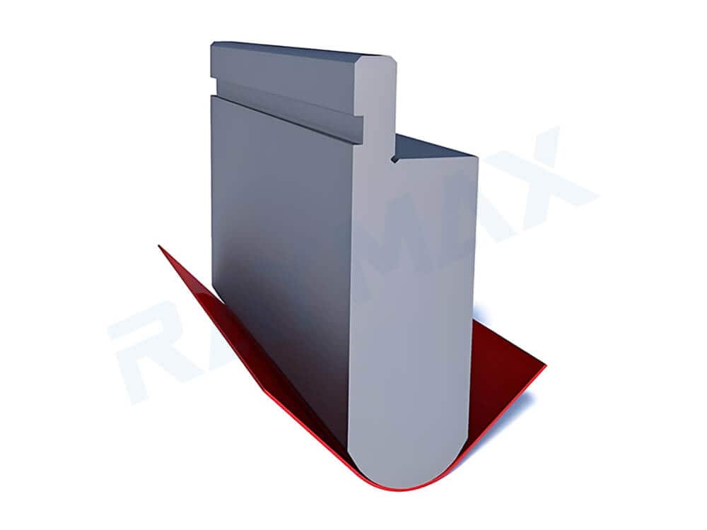
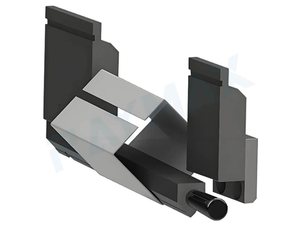
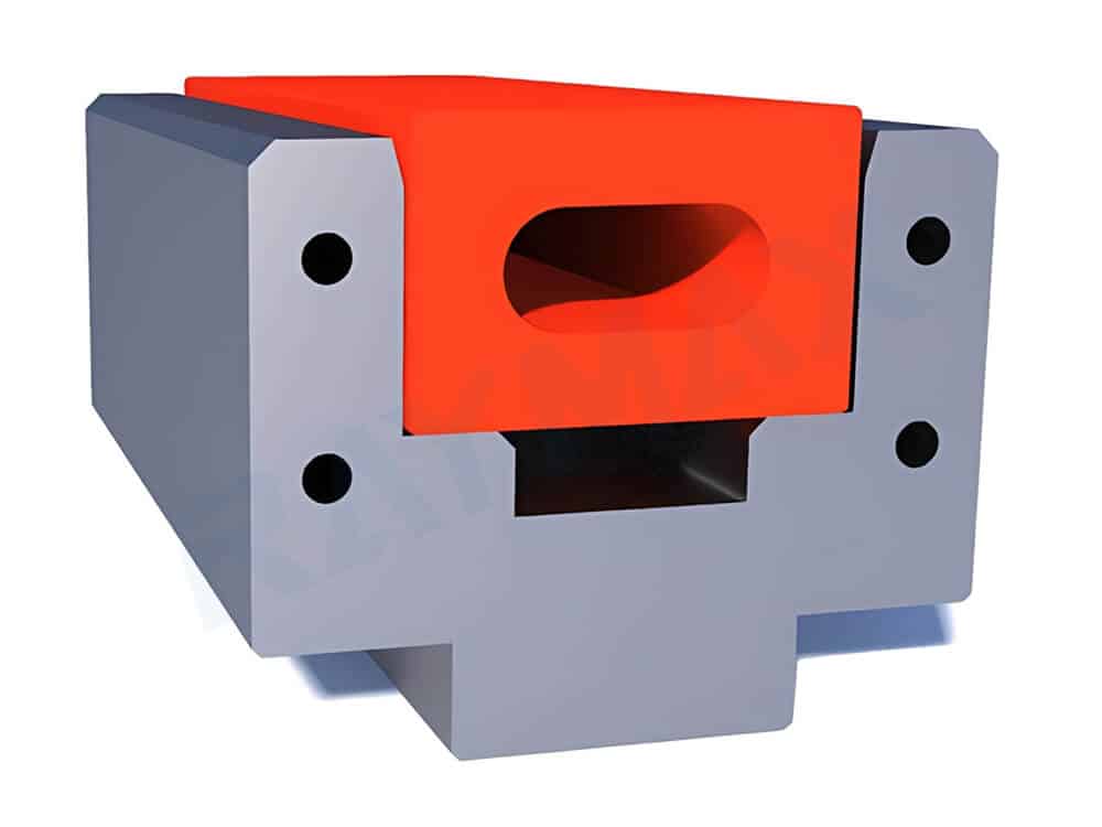
Hemming set
Tooling for flattening / Hemming
Common tooling combinations: Flattening punch paired with a flattening lower die, or hemming punch paired with a hemming lower die.
Suitable applications: Ideal for processes such as edge flattening and hemming. Typically used as a secondary operation following standard bending, it enhances the workpiece’s aesthetic appeal and prevents sharp edges from causing cuts.
Clearance tooling for deep box parts and return bends
Common tooling combinations: Gooseneck punches or deep-profile punches paired with suitable V-dies.
Suitable applications: Suitable for bending deep box-type parts, return bends, box-shaped parts, channel parts, and complex contour parts. When bending deep box-type parts or return bends, the rear-folded edge may collide with the punch or clamping system; clearance tooling provides sufficient clearance to effectively prevent such collisions.
Non-marking tooling for workpieces with high surface finish requirements
Common tooling combinations: Appropriate upper punch tip radius + non-marking lower die / polyurethane / roller-type lower die / protective film or cloth / anti-adhesion solutions.
Suitable applications: Ideal for bending brushed stainless steel, mirror-finished steel, and laminated sheets. Reduces friction, indentations, and material adhesion during bending, protecting the workpiece’s surface. For workpieces with high surface finish requirements, both surface protection and forming solutions must be considered simultaneously during bending. For a more detailed workflow on protective films, polyurethane pads, roller-type lower dies, tooling cleanliness, and handling control, see our guide to preventing scratches during press brake bending.
Heavy-duty tooling for thick plates and high-strength steel
Common tooling combinations: Heavy-duty punch paired with a heavy-duty die.
Suitable applications: Suitable for bending heavy-duty sheet metal such as thick plates and high-strength steel. For these materials, the tooling must possess very high load-bearing capacity, along with long service life and excellent long-term stability.
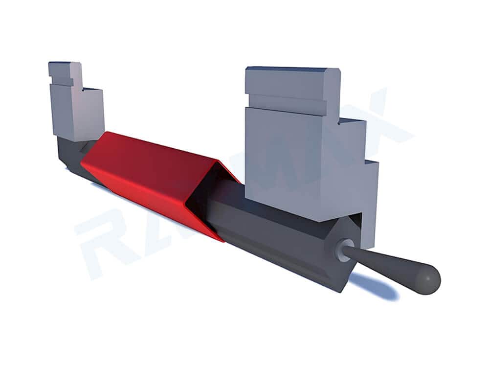
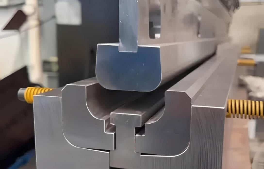
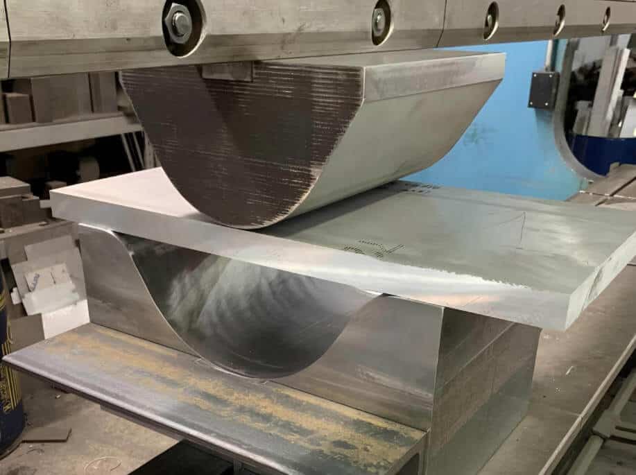
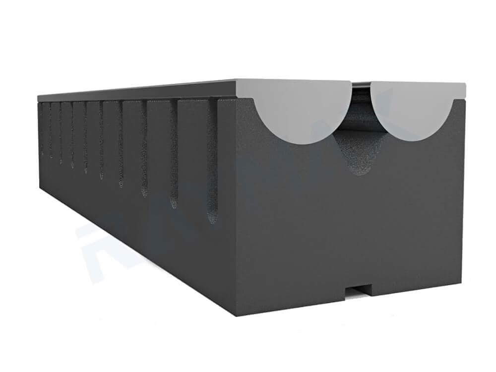
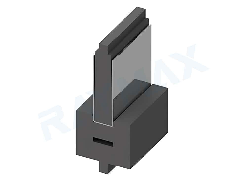
Channel Set
Dedicated Forming Tooling
Common Tooling Combinations: A combination of dedicated upper and lower dies specifically designed for a particular workpiece shape or forming task. A common example is the Channel Set, a combination of punch and die specifically designed for single-pass bending of “U”-shaped channels, which saves time and ensures part consistency. In addition, this category includes dedicated tooling combinations developed for repetitive special profiles, custom-contoured parts, and similar applications.
Applications: Suitable for workpieces featuring numerous slot profiles (such as “U” channels) or special shapes, as well as those with complex contours.
Note: This category does not refer to a basic type of general-purpose upper or lower die, but rather to specialized die solutions developed for a specific workpiece or forming task.
What are the key components of a press brake tooling?
In a real-world workshop, whether a tooling set can operate reliably depends not only on its own function but also on which systems it interacts with and which components affect its performance.
What components make up the tooling body?
Upper punch: This component comes into direct contact with the material, applying downward force to press the material and complete the bending process. It determines whether the workpiece can achieve the target contour; its shape also determines whether it can provide clearance space for the workpiece and may affect the quality of certain bend lines.
Lower die: This component comes into direct contact with the material and is used to support the workpiece, forming a V-opening or other forming contours. It influences the required bending tonnage, inside radius, minimum flange length, and the risk of indentation.
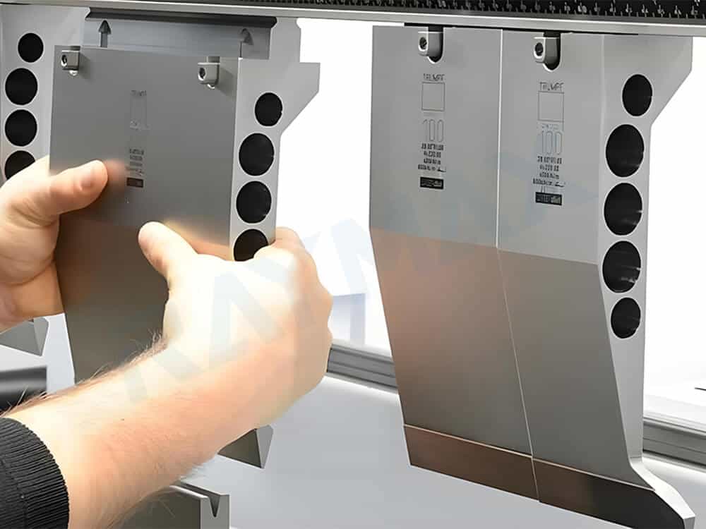
Segmented tooling: These can be divided into standard segments of varying lengths, allowing for flexible assembly based on different workpiece lengths. They are particularly suitable for applications with frequent tool changes.
Tooling height: This refers to the standard height specification of the upper punch and lower die. It determines whether the tooling can be installed smoothly on a specific machine. Consistent tooling heights directly impact tooling combination and subsequent tool change efficiency.
Tooling length combination: Tooling of different lengths can be assembled to accommodate varying workpiece widths. This enhances tooling combination flexibility, which is a key foundation for efficient tooling assembly and changeover.
Tooling shank / Connection: Different tooling shanks come in various shapes, and these shapes determine which compatible mounting systems are suitable. When purchasing, the tooling shank shape must be confirmed before selecting the punch shape.
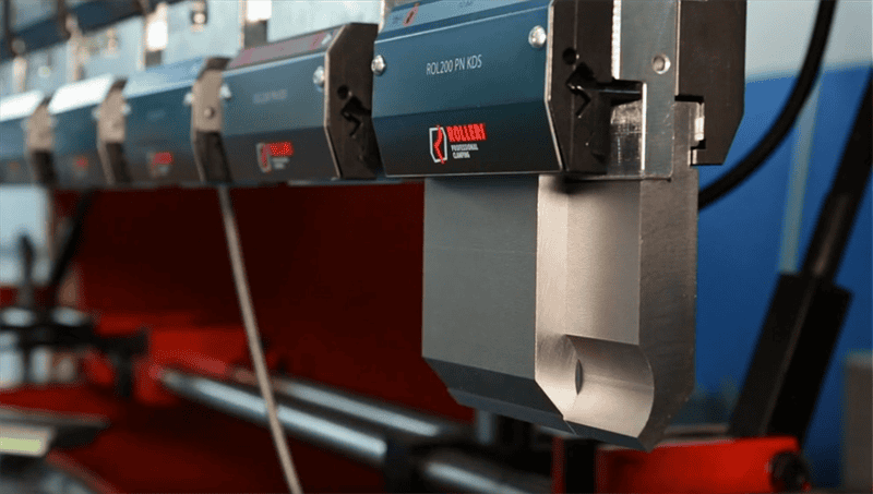
Rolleri Clamping System
Tooling systems directly integrated with the tooling
1. Clamping system: Responsible for clamping the punch, this system typically comes in various types, including mechanical manual, hydraulic automatic, and pneumatic automatic. It determines whether the tooling can be securely clamped and also affects tool change speed, clamping consistency, and repeatability. For workshops that frequently change punches or segmented tooling, a press brake quick clamping system can further improve tool change speed, clamping consistency, and setup repeatability.
2. Lower die holder / die base: This is the base that supports the lower die; it directly affects the stability and installation accuracy of the lower die.
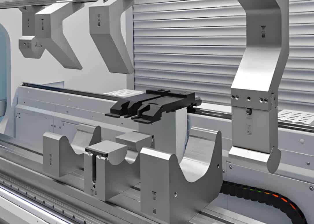
3. Quick-change tooling system: A device that allows operators to load and unload tooling vertically from the front, significantly improving tool-change efficiency while reducing the difficulty of manual handling and minimizing the risk of damage during the process.
4. Segmented tooling management: Used to determine the assembly sequence and workstation layout for tooling of varying lengths, this approach directly impacts tool-change efficiency, workstation reusability, and on-site management efficiency. It is suitable for workshops producing a wide variety of products in small batches with frequent tool changes.
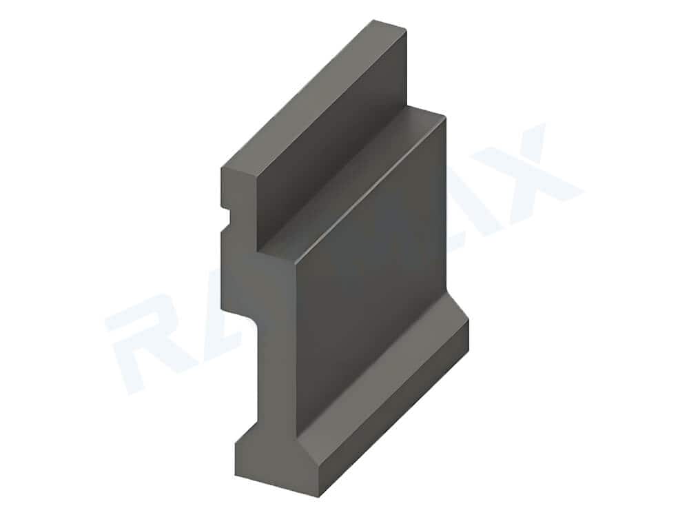
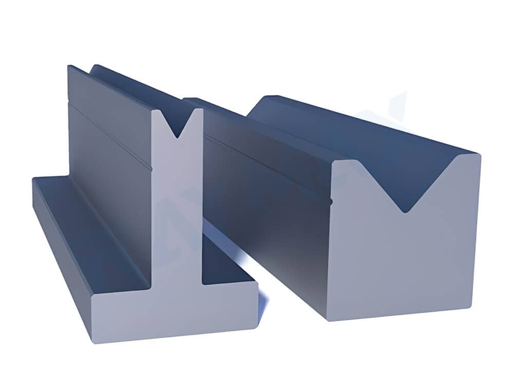
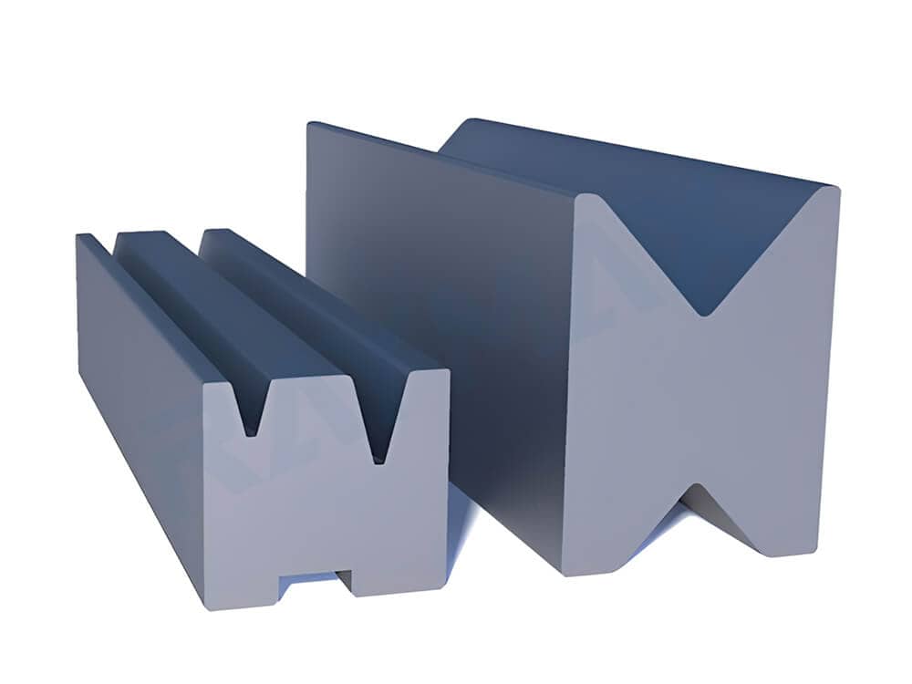
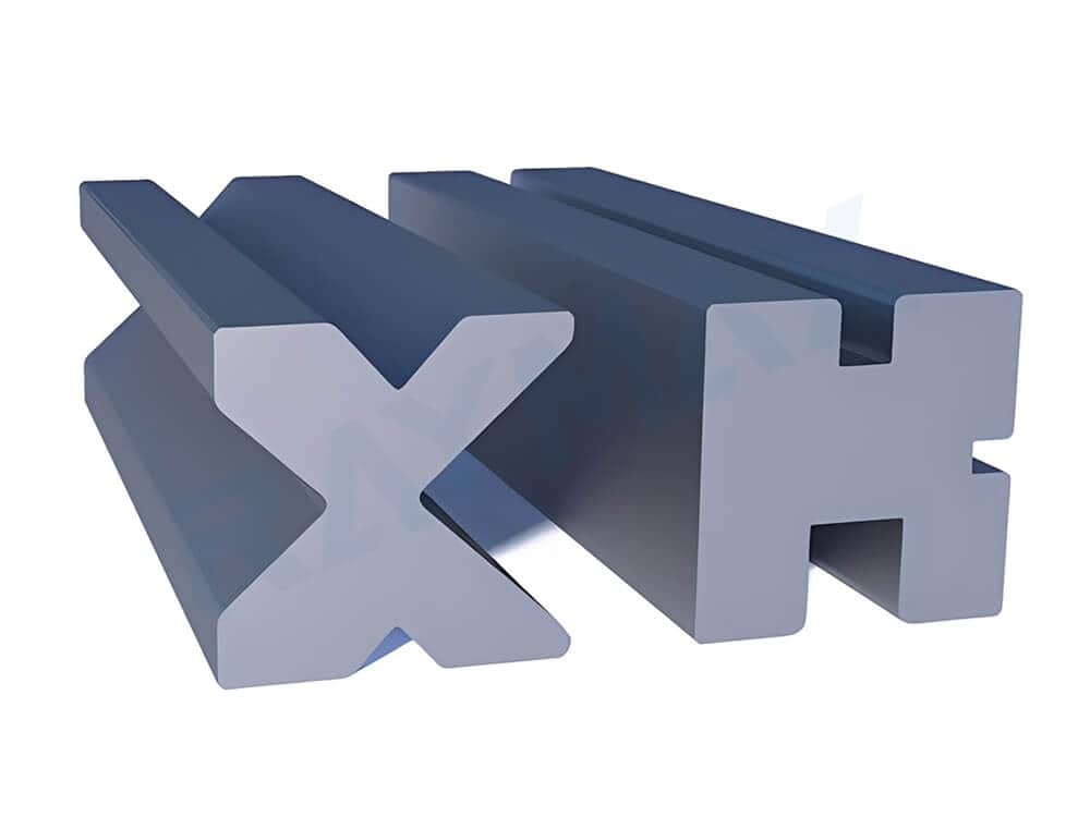
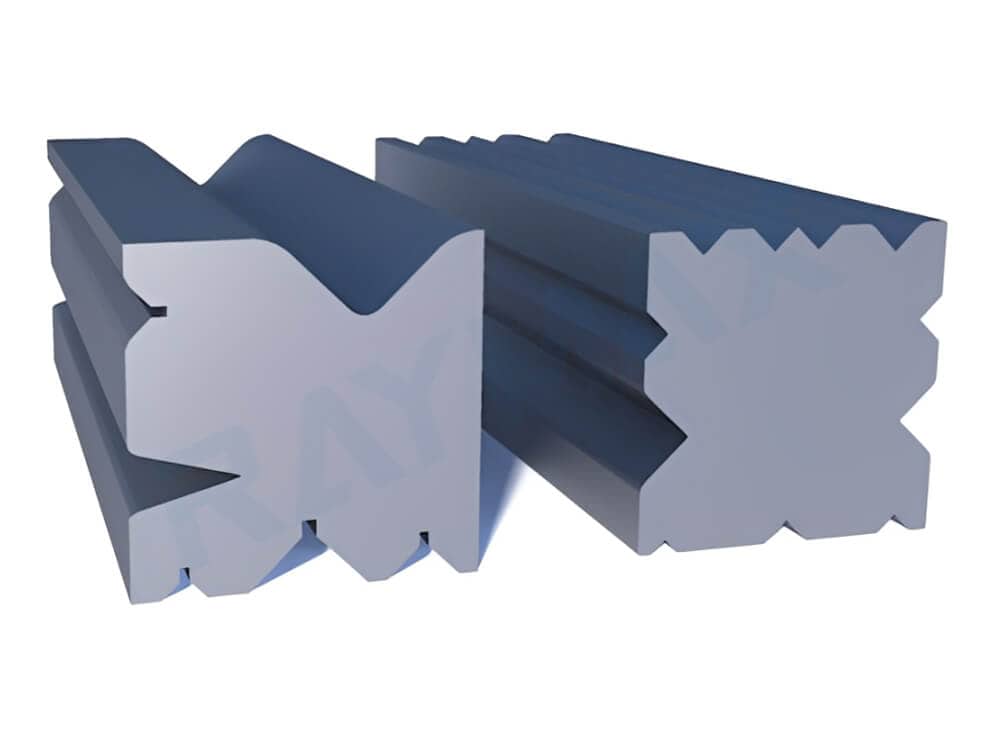
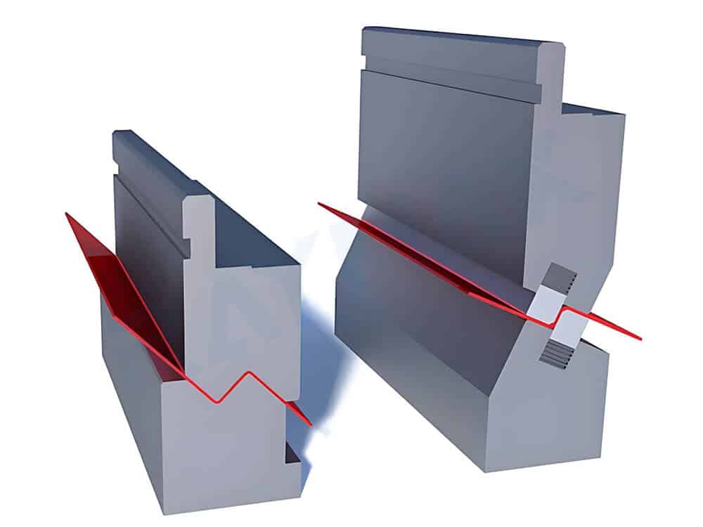
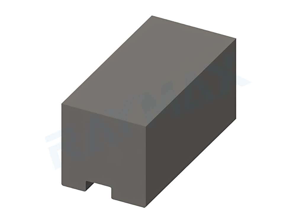
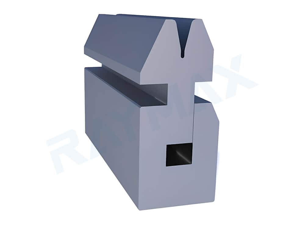
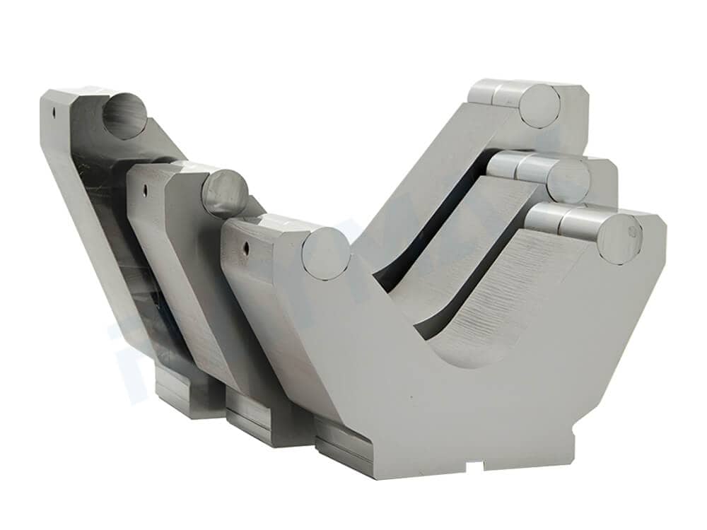
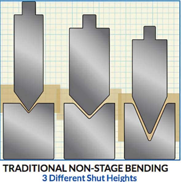
Common Shut-Height Tooling(Staged Tooling Die )
5. Common Shut-Height Tooling / Staged Tooling Die
Features: A die designed so that its shut height matches other compatible dies in the tooling system, even when V-opening sizes differ. This allows multiple die sets to be exchanged or staged on the machine with minimal height readjustment, improving setup efficiency and repeatability.
Applications: Suitable for staged bending, segmented tooling management, standardized production, and operations requiring frequent tool changes.
Illustrate:
Staged Tooling: Because of its design, staged tooling allows different tools to close at the same shut height, so all bending operations can be completed in one progressive setup.
Unstaged Tooling: As the name suggests, unstaged tooling closes at different heights. Therefore, all bending operations cannot be completed in a single setup; otherwise, collisions between the punch and die may occur.
Unstaged Tooling
Staged Tooling
Components that are not part of the “tooling body” but directly affect the performance of the tooling
Backgauge: Used to position the workpiece, ensuring that the bending position remains consistent for each piece. Through precise calculations by the control system, the backgauge block moves along the X-axis to a specified position, thereby ensuring the workpiece achieves the required bending length. It directly affects the workpiece’s bending position, dimensional repeatability, and batch consistency.
Crowning system: Used to compensate for angular deviations caused by deformation of the ram and bed under load during the bending of long workpieces. It plays a significant role in maintaining angle consistency along the entire length of long workpieces.
Control system: Manages ram depth, compensation value retrieval, angle correction, and program synchronization. It directly impacts bending accuracy and batch consistency.
Safety protection devices: Effectively prevent risks arising from operational errors during the bending process. They safeguard the tooling, equipment, and operator. Common forms include laser safety systems, light curtains, side and rear guards, and interlock protection solutions.
Why do many people experience poor on-site results despite purchasing high-quality tooling?
Common causes are most likely related to the following factors: the upper punch and lower dies are not properly clamped; debris or dust is present in the V-die opening; the machine’s crowning value is not correctly adjusted; the repeatability accuracy of the backgauge is insufficient; significant variations in sheet thickness; and operators failing to adjust programs and processes according to different tooling and materials.
Common materials for press brake tooling and differences in service life
Why tooling material matters
Not all tooling made from tooling steel is the same. The material of the tooling directly determines its wear resistance, susceptibility to cracking under high pressure, service life, and whether it can maintain high precision after long-term use.
Understanding common tooling materials
Common tooling materials for general applications: The most commonly used tooling materials are alloy steels or similar grades, which are suitable for most general-purpose bending applications involving thin, medium, and thick sheets. These materials balance wear resistance, cost, and versatility.
Requirements for tooling materials in thick sheet and high-strength steel applications: When bending thick sheets or high-strength steel, using standard tooling results in faster wear and significantly increased failure risks. In such cases, tooling steel with higher strength and greater toughness is required to prevent cracking under extreme pressure.
Why is tooling wear resistance and service life a greater concern in high-frequency production: In high-frequency production, the greatest concern is that tooling wear will compromise bending accuracy or result in an increasing number of indentations and scratches on the surface-sensitive parts. Therefore, tooling wear resistance and service life are critical in high-frequency production.
Why must both material and surface treatment be considered when bending surface-sensitive parts: When bending surface-sensitive parts, we must not only consider the material from which the tooling is made but also its surface treatment capabilities. This is because materials with good wear resistance can reduce tooling wear, thereby minimizing scratches on the workpiece; meanwhile, tooling that has undergone surface treatment can also reduce indentations and drag marks on the workpiece during the bending process.
Key factors affecting tooling life: It’s not just about the material
There are many key factors that affect tooling life. In addition to the material, the following causes may also be responsible:
The bending tonnage exceeds the tooling’s load limit;
The V-die opening is too small, causing excessive stress concentration and resulting in localized overload;
The material is too hard, while the tooling lacks sufficient toughness, leading to tooling damage;
Materials such as aluminum and galvanized sheet metal tend to adhere to the tooling, which can cause surface damage over time;
Improper handling during tool changes can lead to collisions, resulting in chipped corners;
Long-term storage of the tooling in a humid environment can cause rust;
Failure to clean the tooling regularly leads to the accumulation of oil and dust on its surface.
What you should really ask suppliers about materials when purchasing tooling
When purchasing tooling, we should clarify the following key points with suppliers:
What material is the tooling made of?
Is the tooling heat-treated using full-body quenching or just edge quenching?
What is the hardness range of the tooling?
Has any surface treatment been applied?
What are the recommended sheet thickness and material ranges?
What is the maximum load per unit length?
How to select the right press brake tooling
Step 1: First, determine what tooling the machine can accommodate
First, confirm whether your upper punch interface is European, American, or WILA-style; whether the clamping method is mechanical or hydraulic; what the maximum height of the upper punch and lower dies is; and whether segmented tooling is required.
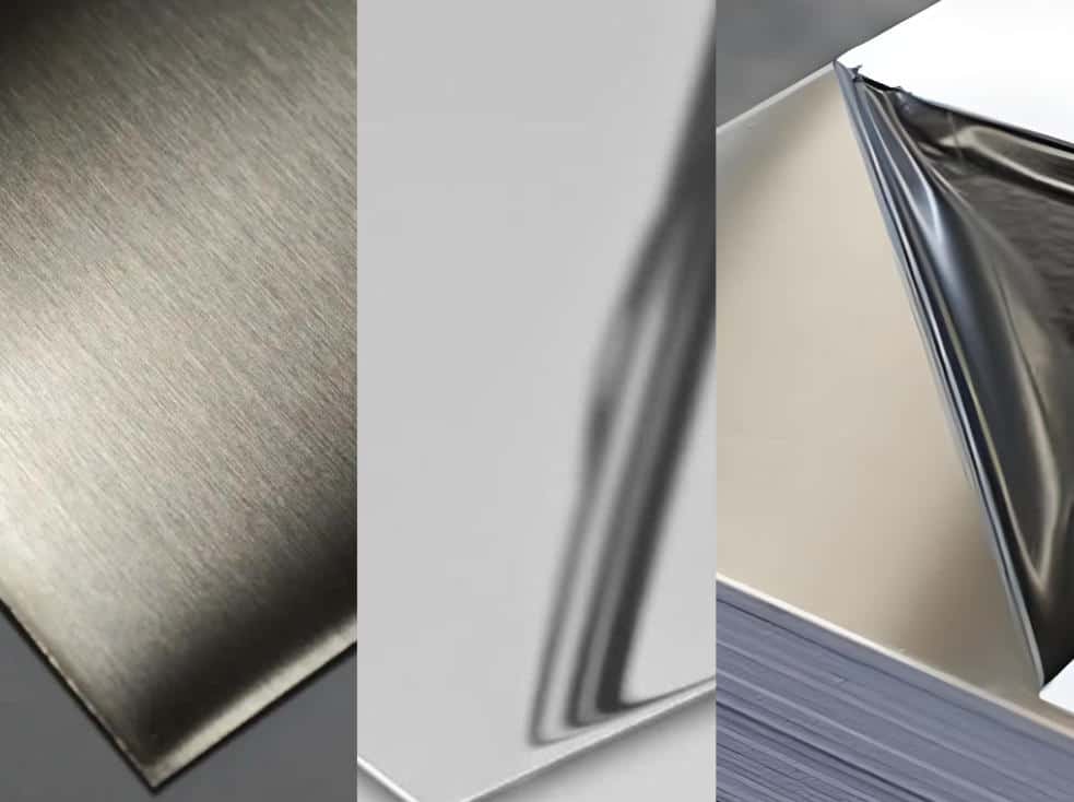
Step 2: Consider the material first, not the angle
Low-carbon steel, stainless steel, aluminum, high-strength steel, and surface-sensitive parts all differ in springback, hardness, and surface sensitivity, which dictates different tooling selection criteria.
For example:
Low-carbon steel is relatively soft with minimal springback; standard tooling combinations are usually sufficient.
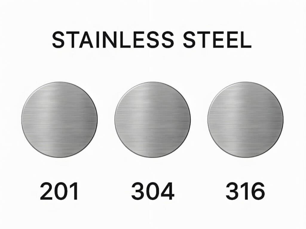
Stainless steel is hard with significant springback and high surface sensitivity; when selecting tooling, pay close attention to the V-opening, surface protection, and angle compensation.
Aluminum and galvanized sheet require special attention to material adhesion and surface damage; when selecting tooling, focus on the radius of the upper punch tip, surface protection, and anti-adhesion solutions.
For high-strength steel and thick sheets, prioritize verifying the tooling’s load-bearing capacity and a larger V-opening;
Surface-sensitive parts have extremely high surface sensitivity, so prioritize non-marking lower dies, polyurethane inserts, or roller-type lower dies.
Step 3: Determine the lower die opening based on sheet thickness and bending method
In air bending, the required V-die opening width varies depending on the type of material.
For example, when bending low-carbon steel, the V-die opening width is approximately 6 to 8 times the sheet thickness (6T–8T); when bending stainless steel, 8T–10T is required; and when bending thick plates, as much as 10T–12T may be needed.
(Note: These are general guidelines, not fixed formulas. If the process involves bottoming or coining, these values will change. Therefore, the final V-opening must be determined based on the material type, sheet thickness, and process method.)
Step 4: Select upper punch geometry based on the target shape
Factors such as the workpiece’s bending angle, the presence of a return bend, and whether the bending space is confined determine which punch shape you should select.
For example:
When bending a standard right-angle edge, a standard punch is sufficient;
When bending a return bend, a gooseneck punch is required;
When the bending space is confined, a narrow-profile punch is needed.
Step 5: Check minimum flange length, interference, and clearance
This is the step beginners most often overlook. If the workpiece’s flange is too short, it may fall into the V-opening during bending; therefore, you must check the minimum flange length on the drawing before bending. Additionally, when bending box-shaped parts, verify that the bending edges will not collide with the tooling or clamping system.
Step 6: Confirm surface quality requirements
Determine whether the workpiece has strict surface quality requirements and whether indentations or scratches on the surface are acceptable. Based on this, assess whether non-marking lower dies or protective measures such as polyurethane pads are necessary.
Step 7: Make the final decision based on production volume, changeover frequency, and budget
If your shop primarily handles small-batch, high-variety production, we recommend prioritizing double-V or multi-V die sets;
If your shop has a high changeover frequency, we recommend prioritizing systems with quick tool changes, such as European-style or WILA systems, and selecting lightweight punches paired with four-sided multi-V die sets; For this type of production environment, it is also worth reviewing compatible press brake attachments and quick-change systems before finalizing the tooling package.
If your workshop frequently produces standard parts in batches, we recommend prioritizing dedicated or custom tooling;
If your products have high surface finish requirements, we recommend prioritizing non-marking lower dies, polyurethane inserts, or roller-type lower dies;
If your products have high precision requirements, we recommend considering bottom or coining processes, selecting dedicated lower dies with corresponding angles and higher-precision control systems, and conducting multiple trial bends if necessary.
Summary of a practical tooling selection process
In summary, we can outline the most practical sequence for tooling selection:
Confirm machine compatibility → Determine the material and sheet thickness to be bent → Select the appropriate bending process → Determine the lower die opening → Select the upper punch geometry → Check the minimum flange length and clearance → Confirm surface quality requirements → Make the final decision based on production volume and budget
press brake tool
How to interpret the most critical parameters of press brake tooling
Why tooling parameters should not be judged solely by “angle” and “dimensions”
If, when purchasing tooling, we focus only on whether they can bend to a specific angle or dimension, we will be presented with many options, leading to the complete neglect of factors that truly matter, such as the V-opening, tooling height, and load-bearing capacity.
The parameters that truly matter are: whether the workpiece can be bent, whether the bending process is stable, whether the workpiece will be damaged by pressure, whether the workpiece and punch will collide, and whether the tooling will be overloaded.
Why is the lower die opening one of the most critical parameters?
Because the lower die opening affects multiple aspects:
It affects the required tonnage: generally, the larger the opening, the lower the required tonnage;
It affects the natural inside radius: In air bending, a larger opening generally results in a larger inside radius;
It affects the minimum flange length: A larger opening generally requires a longer minimum flange length;
It affects the risk of indentation: A smaller opening generally increases the risk of indentation on the workpiece surface;
It also indirectly affects springback behavior: The V-opening affects the natural inside radius, and the natural inside radius, material strength, sheet thickness, and process method collectively influence springback behavior. Therefore, a simple, fixed, one-way relationship between V-opening and springback magnitude cannot be established.
How to understand the punch tip radius
The selection of the punch tip radius is very important.
If the tip radius is too small, stress concentration increases, potentially causing cracks within the metal and accelerating tip wear;
if the tip radius is too large, the desired inside radius may not be achieved.
It is important to note that in air bending, the inside radius formed on the workpiece is typically not equal to the upper punch tip radius, but rather a natural inside radius formed by the interaction of the material, bending angle, and lower die V-opening. Therefore, a more reasonable approach is to first determine what natural inside radius will form under the current conditions, then select a punch tip radius that is as close as possible to this natural inside radius, without exceeding it.
Tool angles and final angles are not the same thing
In air bending, the tooling angle does not equal the final angle of the workpiece, as the final angle is influenced by the bending process, material springback, and press depth. If you want to achieve a more precise angle, consider bottoming or coining rather than simply assuming that an acute-angle tooling will always produce a more precise angle.
Why do issues with minimum flanges always arise?
Whether a minimum flange edge can be bent depends largely on the size of the V-opening. When the flange length is too short and the V-opening is too wide, the workpiece may experience unstable bending accuracy due to insufficient support, or it may fall directly into the lower die, preventing proper forming.
Why must tooling load capacity be verified separately?
Just because the machine has sufficient tonnage for bending does not mean the tooling can necessarily withstand the load. This is especially true when using narrow punches, special punches, or offset punches, in which case it is even more critical to verify the tooling’s load capacity per unit length.
Common selection errors and on-site issues: why some tooling fails to bend properly even after being installed
Selecting the lower die based solely on sheet thickness, without considering the material
Even with the same sheet thickness, different materials vary in strength, ductility, and springback.
Focusing only on whether the desired angle can be bent, without considering the minimum flange
Just because the first piece can be bent to the desired angle does not guarantee consistent results during batch production. If the minimum flange length is too short, there may be insufficient support during the bending process, or the part may fall directly into the V-die opening, resulting in unstable angles.
Focusing only on tooling price, not interface compatibility and clamping precision
The value of tooling lies not in whether it is expensive or cheap, but in whether it is compatible with the machine interface and whether it can clamp securely. If the interface is incompatible or the clamping method is mismatched, even a cheap tooling will increase costs for subsequent trial bending and machine adjustments.
Using standard straight punches for box-shaped parts, resulting in interference
When bending box-shaped parts, if standard straight punches without clearance design are used, the edges bent in the final two steps may collide with previously bent edges. Therefore, when bending box-shaped parts, gooseneck punches or deep-contour punches should be selected.
Using standard lower dies on surface-critical parts results in severe indentations
Sheet metal parts such as brushed stainless steel, mirror-finished parts, and laminated panels have very high surface quality requirements. If standard lower dies are used, they may leave indentations or scratches on the workpiece surface. Therefore, when bending parts with high surface quality requirements, non-marking lower dies should be selected.
Using low-strength tooling in high-frequency production leads to rapid tool life issues
When production frequency is very high, tool wear is the greatest concern. If low-strength tooling is used, wear will accelerate, leading to unstable batch production. Therefore, tooling with higher strength and greater wear resistance should be used.
Mistaking equipment issues for tooling problems
Inaccurate bending angle precision is not always caused by the tooling; it may also be due to issues with the equipment itself, such as: unstable repeatability of the backgauge, improper crowning, deteriorated repeatability of the press brake, or excessive material variation.
Maintenance, storage, and daily management of press brake tooling
If tooling is not regularly maintained and managed after purchase, its surface may wear, accumulate oil and dirt, or become deformed over time. During the bending process, these issues can significantly affect the quality of the workpiece, resulting in problems such as inconsistent angles or surface indentations.
Basic daily inspections
Cleaning: Clean the surfaces of the upper punch and lower die with a clean cloth or brush.
Impact damage inspection: Check the upper punch and lower die for any dents or scratches.
Chip inspection: Use a magnifying glass to inspect the upper punch and lower die for chipped edges or notches, paying particular attention to the punch tip.
Material adhesion: Check the contact surfaces of the V-die opening for any adhered aluminum or zinc shavings.
Rust inspection: Check the tooling surfaces for rust, paying special attention in humid environments.
Operating conditions that are more likely to cause abnormal tooling wear
High-strength steel: Due to its high strength, it requires greater forming force, resulting in higher stress on the tooling and potentially causing cracks.
Galvanized sheet metal: It tends to adhere to the tooling surface, accelerating tooling wear.
Surface-sensitive stainless steel parts: Stainless steel has high hardness, which can easily cause indentations or scratches on the tooling during bending.
Incorrect lower die opening: If the V-die opening is too small, it can cause localized pressure overload, accelerating die wear.
Overloading: Excessive pressure can cause the punch to bend or the lower die to crack.
Most commonly overlooked points during storage
Rust prevention: It is best to store tooling in a dry environment. If conditions do not permit this, rust-preventive oil must be applied to the tooling surfaces.
Preventing impact damage: Do not stack tooling on top of each other; use wooden blocks or foam to separate them. For expensive or specialized tooling, it is best to store them individually.
Segmented numbering management: Clearly label segmented tooling with the product name, segment number, and total number of segments, and arrange them in order during storage.
Storage by height and type: Categorize and store tooling by height and type to facilitate quick retrieval and inventory checks.
When to discontinue use and replace tooling
Tooling should be immediately discontinued and replaced when the following issues arise:
Cracks appear on the tooling surface, or chipping occurs at the punch tip and lower die edges;
Indentations consistently appear on the surface of bent workpieces;
Under the same program and parameters, the angles produced are consistently significantly different;
The tooling falls out or is noticeably loose after installation.
What to confirm with suppliers when purchasing press brake tooling
When purchasing tooling, we should confirm the following checklist with suppliers:
① Confirm the machine brand, clamping system, and interface type
② Confirm the material, sheet thickness, bending process, and primary workpiece shape
③ Confirm whether there are short flanges, and whether the parts are deep box parts, offset bends, or surface-sensitive parts
④ Confirm the recommended lower die opening range and load per unit length
⑤ Confirm the tooling material, heat treatment process, and hardness range
⑥ Confirm the delivery schedule and the segmented tooling configuration plan, and ask whether after-sales support and technical guidance are available.
If a supplier cannot recommend tooling based on your material, thickness, flange size, and part shape, and instead only recommends tooling based on your desired dimensions, then that tooling set may lead to many problems after purchase.
Conclusion
To truly understand press brake tooling, what matters most is not memorizing the names of various tooling types, but learning to determine which tooling to use in specific situations.
The key factors influencing tooling selection typically include interface compatibility, the correct choice of lower die V-opening, the clearance capacity of the upper punch’s geometry, the ability to meet surface finish requirements, and whether the process method is appropriate. For complex workpieces, the choice of tooling must be determined by considering the material, equipment, program, and compensation settings collectively.
We recommend that procurement personnel prepare drawings of typical workpieces, material specifications, sheet thickness, flange dimensions, and equipment information before purchasing tooling, and then consult suppliers for tooling solutions.
If you have any questions regarding tooling selection and press brake fundamentals, please feel free to contact us. Raymax will provide you with professional tooling selection advice.
Ready To Upgrade Your Metal Fabrication Line?
Email Us For A Free Consultation.
Contact us or request a demo
Fill in the form below and our team will be happy to assist you
Frequently Asked Questions (FAQs)
Strictly speaking, their meanings differ slightly in a professional context. In everyday conversation, “tooling” and “tools” are often used interchangeably; however, more strictly speaking, “press brake tooling” typically refers primarily to the upper punch, lower die, and their corresponding clamping/tool-holder systems, while the backgauge, compensation system, and control system are not considered part of the tooling assembly itself.
Choose based on your machine’s interfaces and clamping system. American-style tooling offers greater versatility and lower cost, making it suitable for traditional manual clamping or older press brakes. If precision requirements are not extremely high, this is a good option. European-style tooling integrates more easily with precision clamping systems and segmented tooling, offering high efficiency in tool changes and consistent repeatability, making it suitable for modern CNC press brakes.
This is because the lower die V-opening is not determined solely by sheet thickness; it is also influenced by material properties, bending processes, target inside radius, surface quality requirements, minimum flange length, and machine tonnage. For example, cold-rolled steel and stainless steel of the same thickness have different hardness levels, so the V-opening selection differs; the choice of V-opening also differs depending on the bending process—such as air bending, bottoming, or coining; if the target inside radius is large, a larger V-opening should be selected; for parts requiring high surface finish, a larger V-opening is typically used as well; if the minimum flange length is very short, to prevent the flange edge from falling into the lower die’s V-opening, one should first verify whether a smaller V-opening is feasible; if the equipment requires high tonnage, a larger V-opening should be selected to prevent equipment overload.
This is typically caused by friction between the workpiece and the edges of the lower die’s V-opening. During air bending, as the sheet is pressed into the lower die, the sheet surface often experiences sliding friction against the edges of the V-opening, which easily leaves indentations. To resolve this issue, non-marking lower dies, roller-type lower dies, or polyurethane inserts must be used.
This is usually caused by insufficient clearance capacity of the punch. During the final two steps of bending box-shaped parts, the previously bent edges will curl upward. If a standard straight-body punch without a clearance design is used, the bent edges are likely to collide with the punch. To resolve this issue, a gooseneck punch or a deep-contour punch with a clearance design must be selected.
Machine tonnage does not equate to the unit-length load capacity of the tooling. If narrow punches, special punches, or offset punches are used, their unit-length load capacity is weaker than that of standard punches, making them prone to damage under high pressure. Therefore, when selecting tooling, one must not rely solely on machine tonnage but must also verify the unit-length load capacity.
They can be mixed and matched, but it is essential to confirm that the interfaces, tool height, clamping system, tolerances, and load-bearing capacity are compatible; otherwise, even if they fit, issues such as misalignment, angular deviation, or surface quality problems may arise.
Non-marking lower dies must be considered when the surface quality requirements for the workpiece are very high. Common examples include mirror-finished stainless steel parts, brushed parts, laminated panels, certain aluminum parts, and high-end cosmetic components. For these workpieces, the requirement is not merely to be able to bend them, but also to ensure that the bent surface is free of indentations and scratches.
Tonnage: The bending force required for stainless steel bending far exceeds that of mild steel. Therefore, when…
Post Your Review
Share Your Thoughts And Feelings With Others
We value your privacy
To provide the best experiences, we use technologies like cookies to store and/or access device information. Consenting to these technologies will allow us to process data such as browsing behavior or unique IDs on this site. Not consenting or withdrawing consent, may adversely affect certain features and functions.
Functional
Always active
The technical storage or access is strictly necessary for the legitimate purpose of enabling the use of a specific service explicitly requested by the subscriber or user, or for the sole purpose of carrying out the transmission of a communication over an electronic communications network.
Preferences
The technical storage or access is necessary for the legitimate purpose of storing preferences that are not requested by the subscriber or user.
Statistics
The technical storage or access that is used exclusively for statistical purposes.The technical storage or access that is used exclusively for anonymous statistical purposes. Without a subpoena, voluntary compliance on the part of your Internet Service Provider, or additional records from a third party, information stored or retrieved for this purpose alone cannot usually be used to identify you.
Marketing
The technical storage or access is required to create user profiles to send advertising, or to track the user on a website or across several websites for similar marketing purposes.

-1024x768.jpg)
-1024x768.jpg)
-1024x768.jpg)
-1024x768.jpg)
.jpg)
.jpg)
 Unstaged Tooling
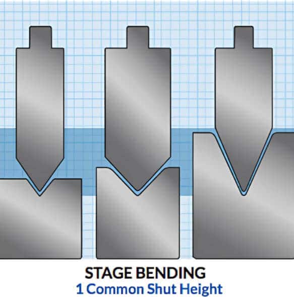 Staged Tooling
-1-1024x768.jpg)
-1024x768.jpg)
-1024x768.jpg)
.jpg)
-1024x768.jpg)