
Francis Pan
Francis Pan is the Foreign Trade Manager of RAYMAX, with over 10 years of experience in sheet metal fabrication equipment and CNC machinery. He has worked closely with manufacturers worldwide on press brakes, fiber laser cutting machines, fiber laser welding machines, and practical production-oriented metal processing solutions.
Top Guidelines
-1024x768.jpg)
-1024x768.jpg)
-1024x768.jpg)
-1024x768.jpg)
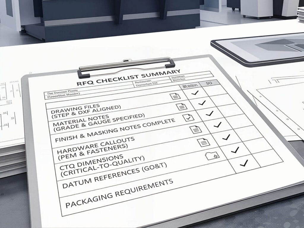
Table Of Contents
Stay in the the loop
Subscribe To Our Newsletter
Introduction
In the automotive manufacturing industry, sheet metal bending is an important process that requires high precision and stability. Parts must meet stiffness requirements while also meeting appearance requirements. Each bend can affect fit-up, assembly quality, and safety, and any small deviation may lead to assembly difficulties. At the same time, facing the pressure of the global supply chain and the requirement for on-time production, lead times are often tight, which means that the bending process must have both speed and stability, minimizing rework and scrap.
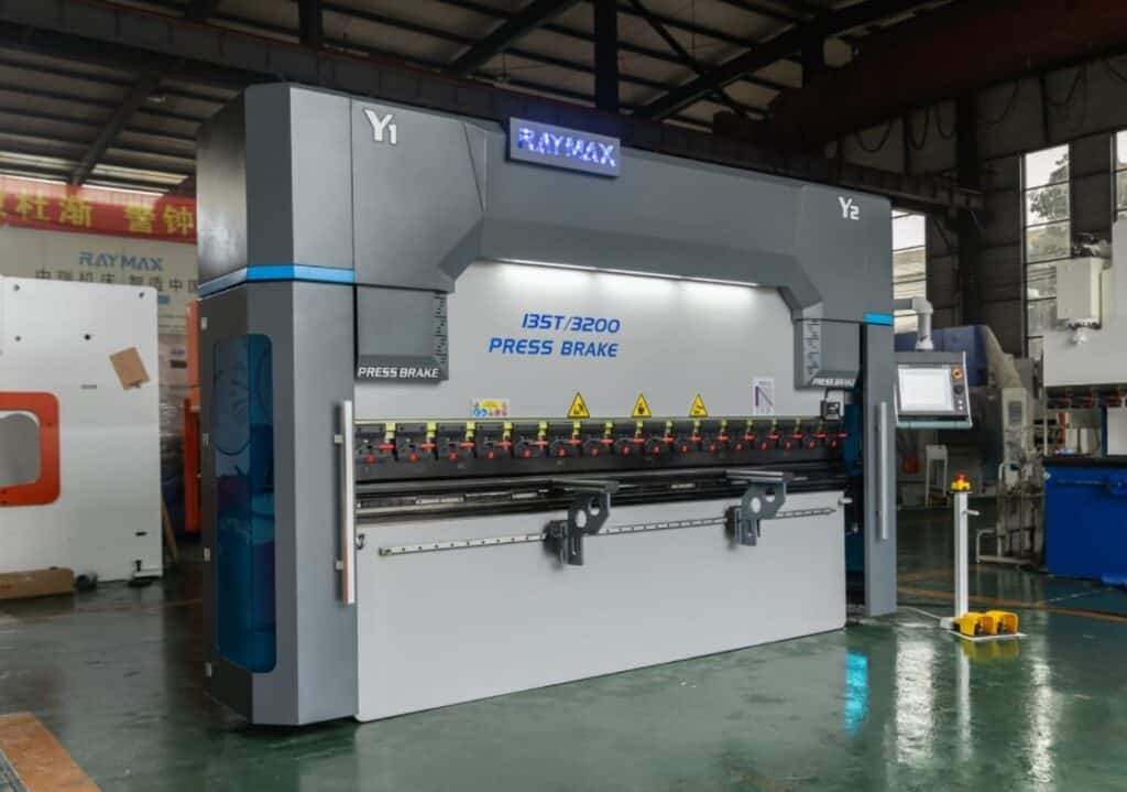
In this article, we will delve into the key points of bending technology, including axis configuration, springback control, quality control, hemming, and surface protection. As a leading sheet metal manufacturer, Raymax focuses on providing advanced metal bending solutions to assist in the production of high-quality automotive components. Share your typical part requirements (material, thickness, max bend length, surface requirements, and throughput). We’ll recommend the right press brake configuration and provide a quote and lead time.
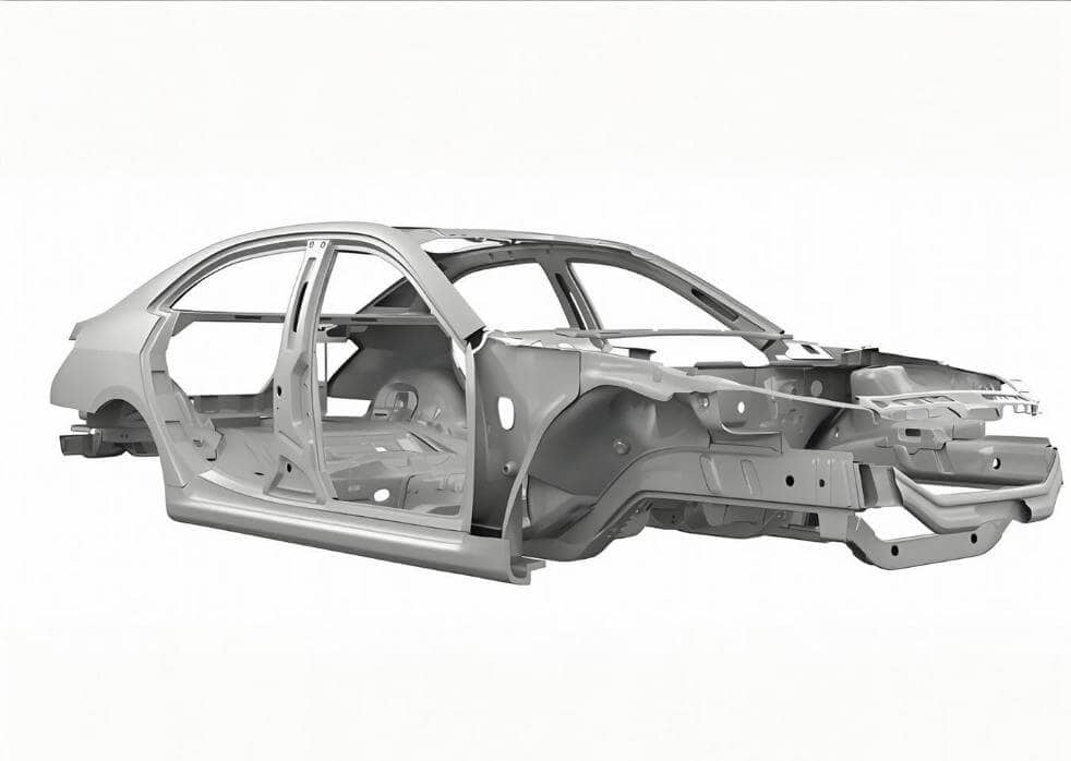
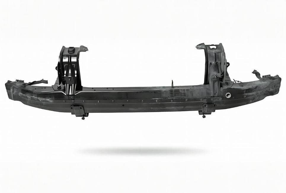
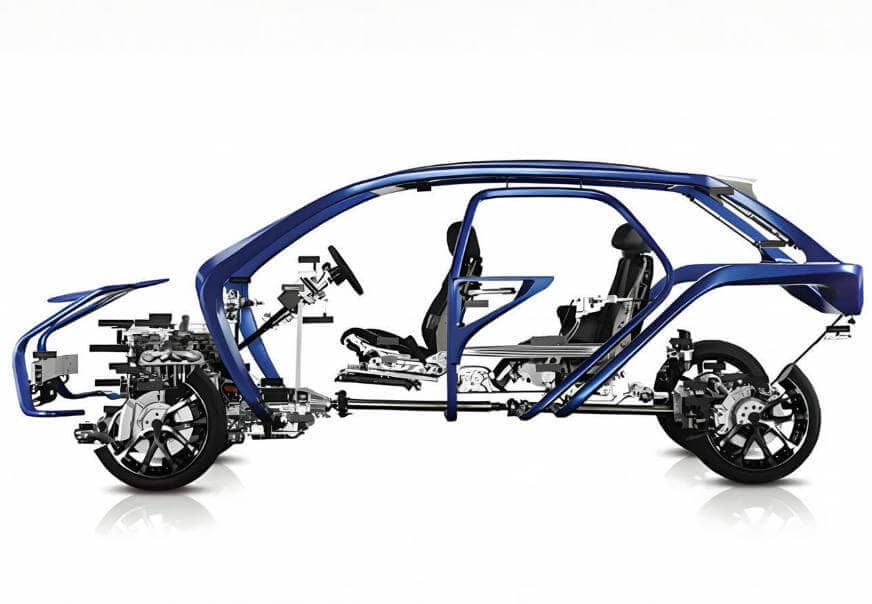
Which automotive sheet metal parts are usually bent using a press brake?
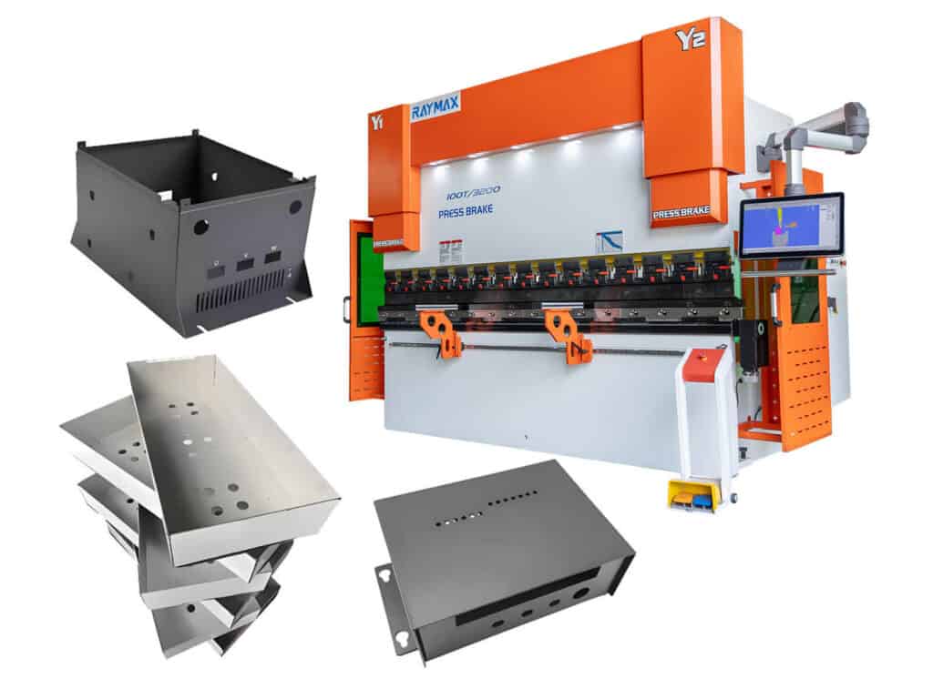
Typical press brake automotive parts (example list)
Typical press brake automotive parts can be divided into two categories: structural parts and Class A surface parts.
|
Material |
Low carbon steel/ galvanized steel |
Aluminum alloy |
Advanced high-strength steel |
Stainless steel |
|---|---|---|---|---|
|
Thickness Range (Example) |
Thin to Medium |
Thin to Medium |
Thin to Medium |
Thin to Medium |
|
Typical automotive components |
Bracket, protective plates |
Body panels, visible brackets |
reinforcements |
shell |
|
Quality priority |
repeatability |
Mark-free bending |
Control springback |
Appearance consistency |
|
Bending method (typical) |
Air bending / Bottoming (depending on CTQs) |
Air bending+protective measures |
Air bending/Bottoming |
bending process |
|
Tooling notes (punch radius / V-opening) |
The V-opening is usually adjusted proportionally with the material thickness (calibration required) |
Larger contact radius; Anti-sticking measures (requires calibration) |
Significant springback; Narrower process window (requires fine calibration) |
Surface smoothness is crucial |
|
Surface protection |
Optional protective film |
Protective film/inserts |
Case-dependent |
Case-dependent |
|
Recommended Axis Configuration |
4-6 axes |
6 axes |
6-8 axes |
4-6 axes |
|
Precautions (springback/compression) |
Stable setup and datum control, controllable springback |
Easy to scratch, sensitive to surface treatment |
There are significant differences between batches, and process control needs to be strengthened |
Risk of scratches or dents |
For stainless steel automotive parts, the stainless steel bending process should be evaluated together with tonnage, V-die selection, springback compensation, and surface protection.
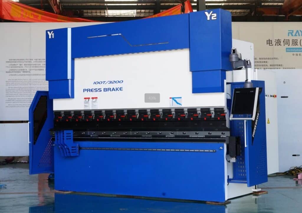
Press Brake and Stamping Machine: When does bending win
Applicable scenarios of press brake: The advantage of press brake is that it can quickly adapt to prototype production and high-mix production. It uses CNC control to achieve consistent angles and flange dimensions, which can quickly bend metal sheets into the designed shape, and the accuracy and forming effect of each operation are stable, suitable for low-to-mid volume production.
Stamping machine applicable scenarios: Stamping machines have high-speed stamping capabilities and can produce a large number of parts in a short period of time, suitable for high-volume production.
According to demand selection: In the initial stage of low production, we can prioritize the press brake; After the scale is up in the later stage, it can be further evaluated to transfer to stamping machines.
Key requirements for the automotive industry: tolerances, angular accuracy, and repeatability
Angle accuracy and dimensional tolerance (why angle determines assembly fit)
In the assembly of automotive parts, the impact of angle deviation on assembly fit is often greater than we expect. Angle deviation can cause the edge of the flange to shift, resulting in misalignment of the hole position and uneven gaps, which may affect subsequent processes.
Repetitive driving factors: synchronous Y-axis + crowning + backgauge repeatability
How to ensure consistent results for different operators and shifts
Cycle time and takt time: How to maintain car bending speed without compromising quality
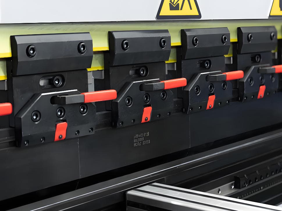
Shorten setup time (quick clamping+standardized tool set)
Running a fast clamping and quick tooling changing system can reduce waiting time and improve processing efficiency.
Standardized tooling setups reduce trial bends and setup time, which can reduce the number of bending tests.
Program reuse and operator guidance (reducing the number of bending tests)
Based on factors such as material type, thickness, and tooling combination, establish a process database that can be directly accessed for processing workpieces of the same type.
Operators need to carefully read the operation manual and proficiently master the entire process from setting, bending, to first article inspection (FAI).
6/8 axis back gauge accuracy reduces repositioning time
More backgauge axes allow the backgauge fingers to reposition automatically, reducing manual moves, re-locating, and cumulative error.
For some complex geometric components, it is recommended to prioritize using 6-axis or 8-axis bending schemes to reduce the number of repositioning times.
What changes occur when automotive materials are bent?
Aluminum automotive parts: Scratch risk+rolling direction+larger bending radius
Advanced high-strength steel: greater springback+requires stronger process control
High strength steel has high strength and hardness, and has greater springback during bending. The angle is difficult to achieve in one go, requiring stronger springback compensation and process control, such as selecting appropriate V-die openings and punch radii.
Material Thickness and Radius: How to Mark on the Drawing
In order to facilitate our selection of the appropriate tooling radius and clarify the processing sequence, we need to indicate these information on the drawing: material grade and status, thickness tolerance, batch requirements, key bending lines, and reference dimension chains.
Springback Control: How to Maintain Angular Consistency in Automotive Production
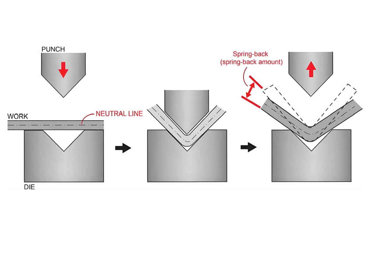
Main reasons for springback
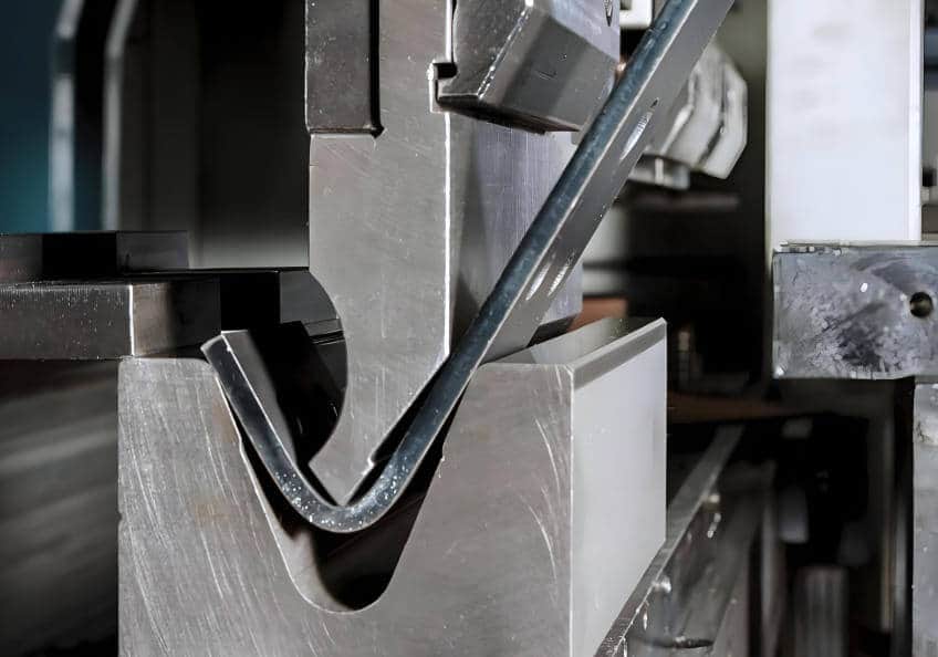
Springback refers to the phenomenon where the metal material undergoes bending processing, the pressure is released, and the elasticity of the material is restored, causing the angle to “open”. Springback can cause angular and dimensional deviations, thereby affecting assembly tolerances. Material strength and thickness, punch and tooling radius, bending method, etc. may all cause springback.
Practical compensation methods
Control of variation: inter batch material+quality control cycle
Surface quality of car panels: mark-free bending and scratch prevention
Source of Traces
Friction, tool contamination, surface roughness of fixtures, incorrect settings, and surface contact during hemming can all lead to panel scratches.
Mark-free solutions
Appearance acceptance criteria: defined in the inquiry form
In the inquiry form, we need to clearly inform the supplier of our appearance acceptance standards. The more detailed we write, the less rework and disputes there will be, and the more stable the delivery will be. We can mainly communicate the following aspects:
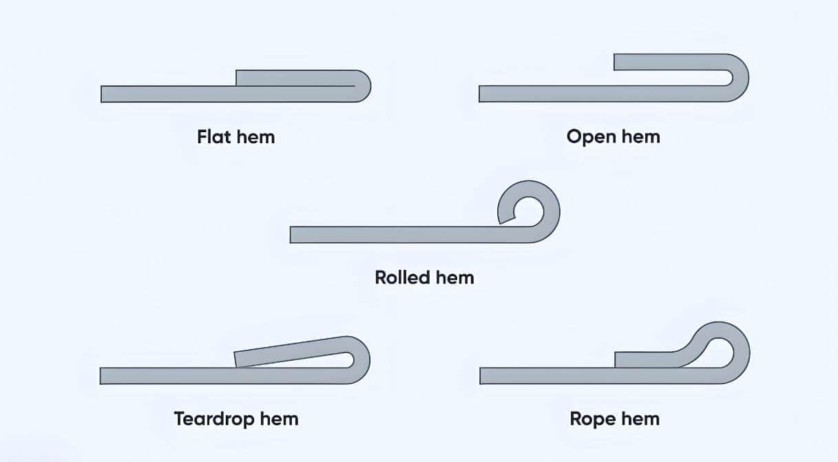
Press brake hemming: applicable scenarios for automotive parts
What is hemming and typical applications in the automotive industry
What is hemming: Folding and flattening the edges to create safe edges, enhance rigidity, and improve appearance.
Typical application: Many structural and decorative parts of automobiles require hemming technology to prevent cutting, enhance edge stiffness, and achieve an aesthetic effect.
hemming tooling options
Design techniques to avoid hemming cracking or uneven hemming
The key limiting factors for hemming are material thickness, minimum bending radius, part geometry, and required hemming tightness.
Design suggestion:
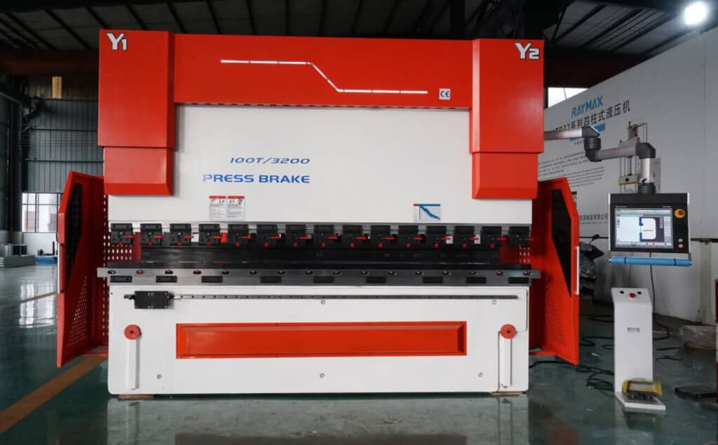
The importance of selecting the number of axes for press brake automotive parts
Functions of each axis
|
Plan |
Quick change fixture (additional) |
|||
|---|---|---|---|---|
|
Cost (relative) |
Low to Medium |
Medium |
Medium to high |
Additional calculation required |
|
Change speed |
Medium |
faster |
optimal |
Enhance greatly |
|
Consistency of complex components |
High (simple components) |
higher |
optimal |
Reduce human error |
|
maintenance |
routine |
Conventional+ |
higher requirements |
Low to Medium |
|
Applicable factories |
General Processing Plant |
Multi variety production line |
CTQ+Automation |
all |
|
Typical automotive components |
Basic brackets |
Multi fold/pallet |
Miscellaneous items |
Frequent replacement of parts |
The influence of precision and repeatability of back gauges on tolerances
The accuracy of back gauge positioning affects the bending angle, clamping position, and final tolerance. The higher the positioning accuracy and repeatability, the stronger the consistency between different shifts and batches of processing, and the more stable the distribution of gaps and tolerances during assembly.
Trade-offs: air bending vs bottoming vs coining
Method comparison and applicable scenarios
Tooling selection: punch radius and V-die opening (practical guide)
Tooling maintenance and calibration (maintaining consistency in the automotive industry)
Regularly check the tip of the punch and the V-die for wear and burrs, keep the surface of the tooling clean and free of oil stains and debris.
Classify and store the tooling in a dedicated tool cabinet, and number them accordingly. Ensure that different shifts use the same set of calibrated tooling.
Common bending defects in automobiles: symptoms, causes, and solutions
Angle deviation and inconsistency
Common symptoms: Inconsistent angle between the left and right ends of the component; Angle drift within the same batch, fluctuating between large and small; The angle changes after changing batches in the same program.
Common reasons: Y1/Y2 synchronization deviation; Not enabled or calibrated for deflection compensation (crowning); The upper and lower tooling are not aligned or worn.
Solution: Execute Y-axis synchronous calibration program in CNC system; Correcting deflection compensation; Re-calibrate the centerline of the tooling, check and replace the worn tooling.
Cracking/wrinkling
Common symptoms: Cracks appear on the outer side of the bend, or a rough “orange peel” texture appears on the surface.
Common reasons: too small bending radius or too small V-die opening; The bending line is parallel to the rolling direction of the material; There are burrs on the edges of the material.
Solution: Choose to increase the punch radius or use a tooling with a larger V-die opening according to the actual situation; Clarify the requirements for rolling direction; Incorporate the quality of edge cutting into the control and bring it to the forefront of the process, or select material grades with better formability.
Traces/Scratches
Common symptoms: Dents and scratches on the surface of the workpiece.
Common reasons: Rough surface and burrs on the workpiece; Tooling wear or metal shavings on the contact surface; The V-opening is too small, causing excessive contact pressure and resulting in indentation; Improper use of mark-free protective tools such as protective films, inserts, and polishing tools; Improper handling leads to friction.
Solution: Remove metal shavings from the tooling, replace worn tooling, or use a larger V-opening; Use protective tools correctly according to requirements and pay attention to handling methods.
|
Defects/Phenomena |
Possible reasons |
Quick investigation |
Corrective Action |
preventive measures |
|---|---|---|---|---|
|
Inconsistent left and right angles |
Y-axis asynchronous/no deflection compensation (crowning)/inaccurate tooling positioning |
Measure the angles at both ends |
Calibration+compensation+spot check |
Routine calibration+tool inspection |
|
There is an error in the length of the flange |
Inaccurate back gauge benchmark |
Check the benchmark edge |
Optimize positioning/increase the number of axes |
Standard Positioning SOP |
|
Excessive springback |
Material thickness issue/bending radius too large or too small |
Sample testing |
Overbending+tooling change |
Create data table |
|
Indentation/scratch |
Tooling contamination/friction/incorrect handling method |
Visual inspection+touch |
Mark-free solution+cleaning |
Cleaning+Clear Acceptance Standards |
|
Edge cracking |
The bending radius is too small/there are burrs on the edge of the material |
Check the location of the crack |
Increase bending radius |
DFM rules+experiments |
Quality Control in the Automotive Industry: First Article Inspection, Process Inspection, and Traceability
First Article Inspection Checklist (Measurement Content)
Before starting mass production, we need to conduct a comprehensive verification of the first part produced, which must meet the requirements of the drawing.
Inspection content:
Process Inspection Frequency (How to Maintain Stability)
Frequency setting:
Sampling inspection content:
(Note: After the first piece is qualified, the process capability is stable, there is a risk of key dimension drift, material/batch replacement, and encrypted sampling must be carried out after tooling replacement.)
Traceability of Repetitive Production Programs/Tooling
When the customer reorders the same part, they require us to be able to replicate 100% of the product with the same quality as the last time. This requires traceability.
Conclusion
Automotive sheet metal bending is a science about precise tolerance control, springback management, and surface perfectionism. To manufacture automotive sheet metal parts with stable bending quality and reduced rework, we need to comprehensively control from multiple aspects such as precision control, cycle time optimization, springback control, surface quality assurance, and hemming.
Share your typical part requirements (material, thickness, max bend length, surface/CTQ requirements, and throughput). We’ll recommend the right press brake configuration and provide a quote and lead time.
Ready To Upgrade Your Metal Fabrication Line?
Email Us For A Free Consultation.
FAQs
Related Blog
Proper setup steps for Press brakes and analysis of common calibration issues
Definition of press brake tool material
-1-1024x768.jpg)
How to Spec a Press Brake for Tolerance: Angle, Flange Length, Crowning, Backgauge & Acceptance Checklist
What Is a Sheet Metal Press Brake Machine? Working Principles, Bending Techniques & Buying Guide
-1024x768.jpg)
10 Common Press Brake Air Bending Problems: Causes, Troubleshooting, and Fixes
Press Brake Quick Clamping System: Types, Compatibility & How to Choose (Quick Clamp Guide)
Press Brake Radius Mastery: Inside/Outside Radius, 8× Rule, and Real-World Tips
Press Brake Air Bending: Guide to Principles, Calculations & Best Practices
Electrical Enclosure Bending: Flat Pattern, Flange Accuracy & Fit-Up Issues
a guide to 11 Types of press brake bending process
.jpg)
Stainless Steel Bending Force: 304 vs 316 (Correction Factors, Springback & V-Die Selection)
Press Brake RFQ Checklist: 14 Fields You Must Provide for an Accurate Quote
Post Your Review
Share Your Thoughts And Feelings With Others