
Francis Pan
Francis Pan is the Foreign Trade Manager of RAYMAX, with over 10 years of experience in sheet metal fabrication equipment and CNC machinery. He has worked closely with manufacturers worldwide on press brakes, fiber laser cutting machines, fiber laser welding machines, and practical production-oriented metal processing solutions.
Top Guidelines
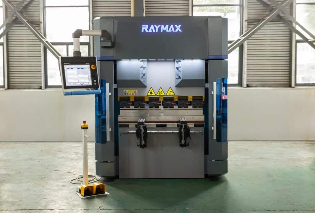
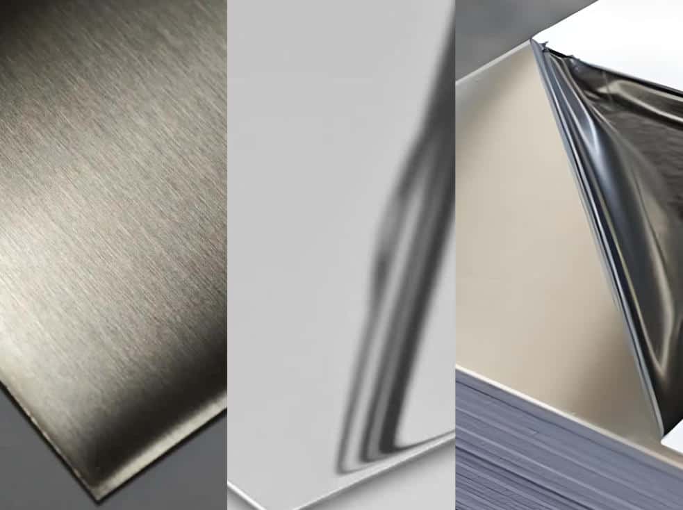
-1024x768.jpg)
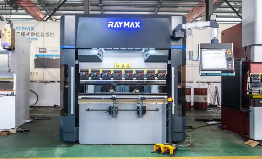
-1024x768.jpg)
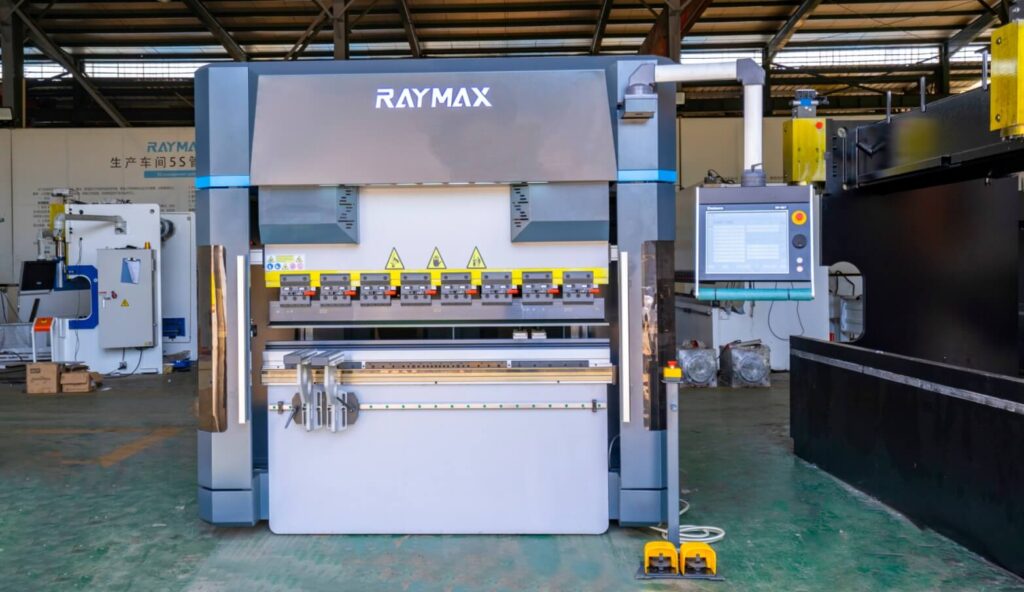
-1024x768.jpg)
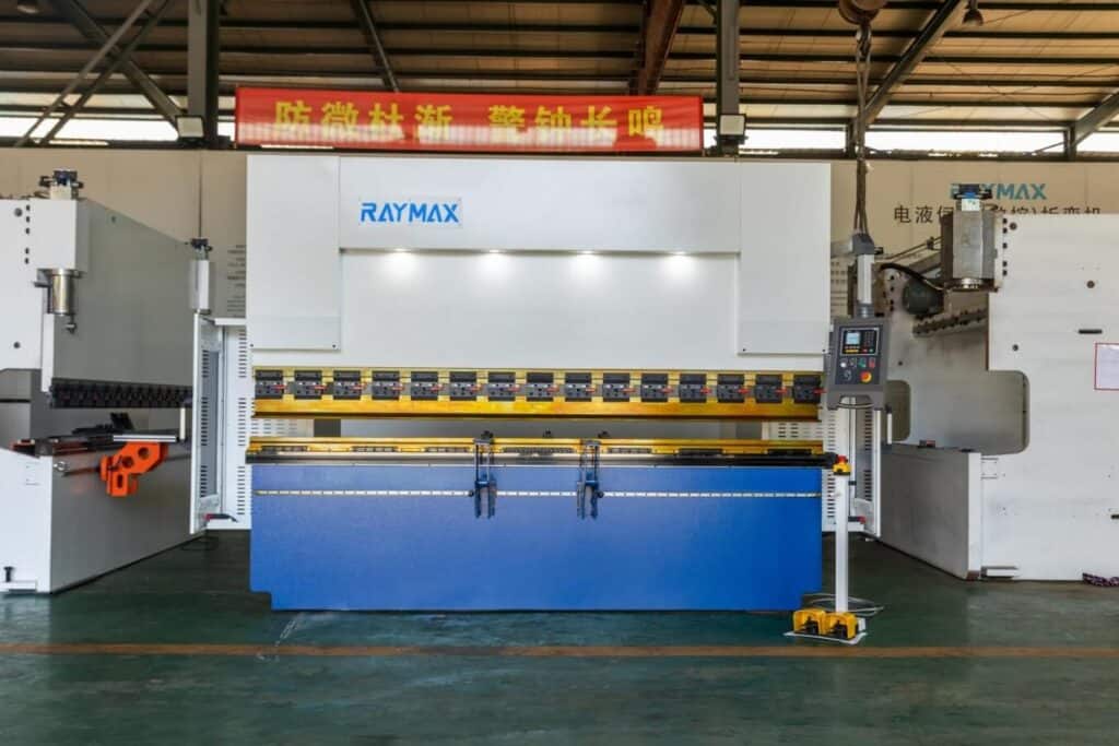
-1024x768.jpg)
Table Of Contents
Stay in the the loop
Subscribe To Our Newsletter
Opening summary: Identify the error type first — don’t change the program first!
Backgauge accuracy problems usually show up as unstable flange length after bending, inconsistent left and right dimensions, dimensional drift during batch production under the same program, or cumulative error that grows larger after multiple bending steps. To troubleshoot backgauge accuracy problems, do not change the program first. Identify the error type first.
The correct sequence of troubleshooting is:
Identify the type of error → verify the CNC displayed position against the actual position → check the mechanical transmission and backgauge finger parallelism → check the CNC parameters and servo feedback → check whether it is a problem of operation and workpiece datum → trial bend to confirm.
This article explains how to identify error types, follow a proper calibration process, and use preventive maintenance to diagnose flange length errors more quickly.
30 second quick check
|
Shop-floor symptom |
Primary suspect |
First check |
|---|---|---|
|
Fixed oversize or undersize for each piece |
Backgauge zero point error, X-axis offset parameter error, program datum error |
Measure the actual distance from the backgauge finger contact face to the die centerline with a measuring tool and compare it with the CNC display. |
|
Random fluctuations in size for the same program |
Ballscrew backlash, guide rail contamination, loose coupling, unstable servo feedback. |
Continuous back and forth positioning and record the data of each measurement. |
|
Left and right flange lengths are inconsistent |
Backgauge finger misalignment, beam misalignment, workpiece resting on only one backgauge finger. |
Measure the distance from the contact face of the left and right backgauge fingers to the V-die centerline to see if the left and right positioning datums are the same. |
|
Normal in the center station, but deterioration in the two side stations |
Beam misalignment, localized guide rail wear, abnormal backgauge finger position |
Do the left, center and right full-stroke positioning test. |
|
The size starts to drift after changing materials |
Material thickness fluctuation, springback variation, quality variation of cutting edge |
Check the quality of material lot and edge first, don’t move the backgauge first. |
|
Cumulative out-of-tolerance error after several bending passes |
Wrong bending sequence, wrong positioning datum, abnormal backgauge finger position, unstable workpiece positioning against the backgauge. |
Check whether the positioning datum of workpiece positioning against the backgauge is consistent at each step of the process. |
|
The backgauge moves with a strange noise or jamming |
Contamination of the guide rail, insufficient lubrication, ballscrew wear |
Clean and lubricate the guide rail, and run the machine without load to check whether there is any resistance. |
|
CNC display is correct but the actual position deviates |
Backgauge zero point error, axis parameter error, encoder feedback abnormality |
Measure the actual position of the backgauge finger with a measuring tool, check the parameters and alarm records. |
The Backgauge Is More Than a Positioning Device — It Directly Affects Flange Length
Why does the backgauge have a direct influence on the flange length?
The backgauge is the dimensional reference before bending. It controls the distance between the workpiece edge and the bending line, so it directly affects the final flange length — and it is the first link in the dimensional positioning chain to be checked. Once the backgauge position is wrong, the bend line may be offset from the beginning, and even if the angle is accurate, the final flange edge may still have a large error. If the machine has not been purchased yet, define your flange length tolerance requirements before deciding the backgauge configuration.
For electrical cabinets, chassis, brackets, doors, panels, and box-shaped workpieces, the flange length error in the assembly will easily expose a lot of problems, such as holes cannot be aligned, edges and edges are not aligned with each other, welding difficulties, etc., and even the entire batch of workpieces need to be reworked or scrapped directly.
Why is the size of the workpiece still wrong when the CNC display is correct?
The CNC display value being correct only means the control system believes the target position has been reached — it does not mean the backgauge finger contact face, the die centerline, and the workpiece reference edge are all truly aligned.
In the process from CNC command to finished bend, the final size of the workpiece will be affected by a number of links, including: backgauge zero point, the status of the ballscrew and guide rails, backgauge finger contact face condition, beam parallelism, die centerline, the quality of the edge of the sheet, workpiece positioning against the backgauge action and the positioning datum after multiple bending steps. Mechanical clearance, loose backgauge fingers, beam misalignment, incorrect tooling data, and the workpiece seating action can all turn a “correct display” into a “wrong part size.” For a basic explanation of the backgauge structure and its main components, see our guide to press brake back gauge structure and key components.
Therefore, to ensure correct workpiece size, do not rely on the CNC display value alone — always measure the actual position with a measuring tool, and then conduct a trial bend to verify.
Check the dimensional datum chain first, not just the backgauge value
Flange length cannot be determined by looking at a single number on the CNC screen. It is controlled by a complete datum chain: drawing dimension → cut edge of the sheet → backgauge finger contact face → actual X-axis position → bending line → inside bend radius. If there is any error in any of these steps, the final flange size will not match the drawing.
Therefore, when we are troubleshooting backgauge problems, we need to check each link step by step to see which one is wrong.
Which workpieces are most likely to expose backgauge accuracy problems?
Workpieces that are likely to expose backgauge accuracy problems include:
The longer the workpiece and the more bending processes, the more obvious the backgauge accuracy problem will usually be exposed.
Identify the Error Type Before Changing Parameters
Fixed deviation — each piece is off by the same amount
Random drift — the same program gives a different result each time
Unequal length of left and right flanges
.jpg)
Dimensions deteriorate after moving to a different station
Cumulative out-of-tolerance error after multiple bending steps
Explanation: Positioning accuracy vs positioning repeatability vs backlash
|
Concepts |
Field meaning |
Typical performance |
|---|---|---|
|
Positioning accuracy |
Whether the actual position is the same as the set position |
Each flange length is fixedly larger or smaller. |
|
Positioning repeatability |
Can the backgauge return to the same point after several round trips? |
Random fluctuations in size with the same program |
|
Backlash |
Approach the same point from the front and rear directions, whether the result is the same. |
Inconsistent dimensions after direction change |
|
Parallelism |
Is the distance from the left and right backgauge fingers to the die centerline the same? |
Inconsistency between left and right flange lengths |
If you need a broader comparison between accuracy and repeatability in bending, read our guide on positioning repeatability vs accuracy.
Do these 4 basic tests first, don’t skip a step!
If only an edge of the lower die can be used as the measuring reference, the fixed offset from that edge to the V-die centerline must be confirmed first, otherwise the measured value cannot directly represent the real X-axis positioning distance.
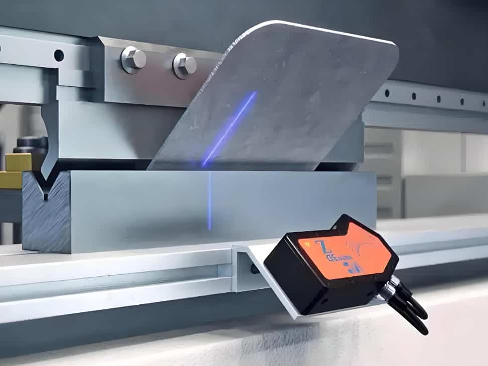
Test 1: Comparison between CNC display value and actual position
This test is the starting point of all the troubleshooting, if the parameters are adjusted directly without first conducting actual measurement, the adjusted parameters will be meaningless.
Test 2: Repeat positioning test
Poor positioning repeatability of the backgauge indicates that its mechanical chain or feedback chain has been unstable, in this case there is no way to solve the problem just by one calibration, it is necessary to carefully check the wear and looseness of the mechanical parts and the accuracy of the servo feedback, and repair or adjust it.
Test 3: Left and right backgauge finger parallelism test
Some small deviations may not be visible on the short workpiece, but will be magnified on the entire bend line of the long workpiece.
Test 4: Actual trial bend verification
The purpose of no-load measurement is to confirm whether the position of the machine is accurate, and the purpose of trial bend verification is to check whether the actual processing results meet the requirements. When both checks are qualified, it is considered to have completed a comprehensive inspection and confirmation of the backgauge problem. For a more complete machine-level inspection list, use this press brake bending accuracy checklist.
Mechanical layer checking — start from here, do not skip layers!
Ballscrew Backlash
Compensation cannot solve the mechanical problem fundamentally. If the compensation value is increasing, it means that the ballscrew backlash is continuously expanding, and at this time, we should prioritize checking, repairing or replacing the mechanical structure instead of relying solely on the compensation function.
Linear Guide Rails and Slider Blocks
The backgauge is a precision motion system, if the guide rail surface is dirty or worn, then the backgauge positioning may not be able to ensure long-term stability.
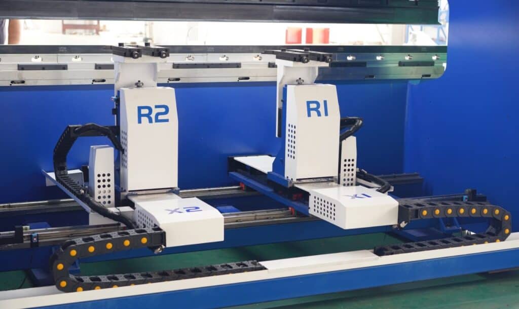
.jpg)
Loose coupling and motor installation
The fact that the servo motor is running does not mean that the ballscrew is also moving accurately. Any looseness in any part of the transmission chain may cause errors in the dimensions of the workpiece.
Loose, Worn, or Deformed Backgauge Fingers
The backgauge fingers are the reference for workpiece positioning, and their position and condition directly affect dimensional accuracy. If the backgauge fingers are bent, worn, or not at the same height, there is no guarantee that the backgauge positioning will be accurate, even if the backgauge system is accurate.
Backgauge Beam Misalignment or Deformation
If the beam is not parallel, even if the program is accurate, the set datum is most likely wrong.
CNC and Electrical Troubleshooting — Check This Layer Only After the Mechanical System Is Stable
Zero or reference point error
The zero point of backgauge is the starting point of all machining positions, Once the zero point is wrong, all subsequent position data may be offset.
Axis offset or scale factor error
Abnormal encoder or servo feedback
Program data and tooling data error
Once the tooling data is wrong, the backgauge position calculated by CNC may be wrong. After tooling change, if you do not update the tooling library in time, you are using the old datum to process new workpieces.
Operation and workpiece layer checking — not all out-of-tolerance errors are caused by the backgauge
The Sheet Is Not Fully Seated Against the Backgauge Fingers
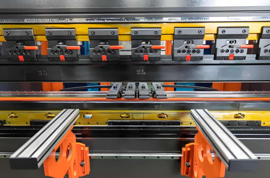
.jpg)
The Workpiece Tail Hits the Backgauge Fingers During Bending
Burrs and Poor Cut Edges Cause False Positioning
.jpg)
Wrong datum selection for multiple bending steps
How to check X-axis, R-axis and Z-axis respectively?
X-axis — directly determines the flange length.
If it is a simple part, you usually only need to pay attention to the X-axis. If it is a complex part, you must pay attention to the X-axis, R-axis and Z-axis at the same time.
R-axis — affects the backgauge finger height and the stability of multi-pass bending
R-axis is very important in the processing of complex parts. Once the backgauge finger height is wrong, the workpiece positioning datum may change.
Z-axis — affects left/right positioning and workpiece positioning against the backgauge for complex parts
The Z-axis determines whether the backgauge fingers are in the correct position. Once the backgauge finger position is wrong, the workpiece may lean against the backgauge or contact only one backgauge finger.
What is the value of a multi-axis backgauge?
The value of a multi-axis backgauge system is not so much that the more axes you have, the more accurate it is, but rather that it allows for more flexible positioning of complex workpieces, provided that the machine structure, control system, calibration process, and operating habits are all stable.
For deep box parts, shaped parts, multiple-bend parts, and left-right asymmetric parts, multi-axis backgauge can reduce manual positioning errors and increase the degree of freedom of positioning.
.jpg)
Standard procedure for backgauge calibration
Before cleaning, measuring, adjusting the backgauge fingers, checking the guide rails or ballscrew, it is necessary to stop the machine and cut off the power supply or control the related moving parts according to the equipment maintenance regulations.
Particular attention should be paid to the fact that you cannot reach into the work area for measuring or cleaning operations while the ram, tooling and backgauge are in motion.
Step 1: Stop the machine, clean, and check for impact marks
Before calibration, clean the guide rails, ballscrew, backgauge finger contact face, and sensor sensing surface, and check whether the backgauge fingers have been deformed by a collision, whether bolts are loose, whether the beam is deformed, whether the sensor mounting is loose, and whether the guide rails and ballscrew show visible contamination.
If these basic conditions are not met, the accuracy of the backgauge cannot be guaranteed.
Step 2: Confirm mechanical parallelism
Measure the parallelism between the backgauge beam and the bending line, and confirm the distance from the left and right backgauge finger contact faces to the die centerline, covering at least the left, middle and right positions.
In the horizontal direction, make sure that the backgauge beam is parallel to the bending line; in the vertical direction, check whether the heights of the left and right backgauge fingers are the same, and confirm whether the R-axis height matches the currently used tooling and workpiece.
It is not enough to measure only one direction or one work station, which can only prove the status of a certain part, and there is no way to guarantee that the positioning accuracy of the whole backgauge system is accurate.
Step 3: Calibrate the actual X-axis position
First set the standard position, then measure the actual position, compare the displayed value with the measured value, then adjust the axis offset or calibration value, and finally repeat the verification.
If it is a high-demand scenario, at least measure multiple positions of the near end, middle section and far end. Be careful not to correct too much at one time, and re-measure and trial bend after each adjustment.
Step 4: Confirm the R-axis height and Z-axis backgauge finger position
Firstly, check whether the R-axis height is suitable for the current tooling, and also check whether the heights of the left and right backgauge fingers are the same;
Secondly, adjust the Z-axis backgauge finger position to make sure that it can avoid the holes, notches and shaped edges on the workpiece.
In the case of multi-pass bending, it is also necessary to confirm whether it is necessary to set a backgauge retract movement, including X-axis retract, R-axis height adjustment and Z-axis backgauge finger avoidance. Only when the R-axis and Z-axis parameters are set accurately, the workpiece can be stably seated at the correct position.
Step 5: Trial bend verification and build a calibration record
After calibration is completed, trial bend verification must be done to record the flange length, left and right dimensions, bend angle and total dimensions after multiple bends, and to confirm that there will be no interference in the assembly.
In the calibration record, note down: date, operator, machine number, tooling number, material information, set values, measured values, adjusted values and final trial bend results.
Documenting the complete calibration results is the only way to see if there is a gradual decline in accuracy or a sudden jump.
Printable Test Record Sheet
|
Test items |
Setpoint |
Actual measurement |
Deviation |
Error type judgment |
Processing action |
|---|---|---|---|---|---|
|
X axis fixed position test |
Fixed deviation/random drift |
||||
|
Repeat Positioning Test |
Positioning repeatability is stable or not |
||||
|
Left backgauge finger distance |
Consistency between left and right |
||||
|
Right backgauge finger distance |
Consistency between left and right |
||||
|
R axis height |
Consistent height |
||||
|
Z-axis backgauge finger position |
Suitability for workpieces |
||||
|
Trial bend flange length left side |
Verification of actual processing |
||||
|
Trial bend flange length right side |
Verification of actual processing |
Preventive maintenance rhythm – stabilizing accuracy over time
Maintenance rhythm table
|
Frequency |
Required action |
|---|---|
|
Before each shift |
Clean the backgauge finger contact faces and guide rails, check the bolt fastening status, and observe whether the backgauge moves smoothly. |
|
Weekly |
Check the lubrication status, and make a record of positioning repeatability spot checks. |
|
Monthly |
Check the X-axis datum and the parallelism of the left and right backgauge fingers at the usual working positions. |
|
After a collision |
Stop the machine to check the actual position of the backgauge fingers, beam and X-axis and make a trial bend. Do not go straight into batch production. |
|
After replacing critical parts |
Re-calibrate the relevant axis parameters and do a trial bend to verify. |
|
After batch part size starts to drift |
First distinguish what type of error, then follow the sequence of mechanical, parameter, electrical and operation to check. |
Key judgment
If accuracy gradually declines, mechanical component wear is the first suspect. If accuracy shifts suddenly, first check whether a collision has deformed the backgauge fingers, shifted the backgauge zero point, or changed the axis parameters.
How does the backgauge configuration affect long-term accuracy? What to ask when selecting a machine
Don’t just look at the number of axes — look at the overall capability of the backgauge system
When purchasing a press brake, you can’t just focus on how many axes the backgauge has, but rather look at the structural rigidity of the backgauge, the stability of the servo control, the positioning repeatability detection method, the number of axes supported by the controller and synchronization function, whether the factory has a precision testing process and after-sales calibration guidance.
The most critical thing about the backgauge is its positioning repeatability, not the number of axes.
Which customers need a higher-spec backgauge?
When your main products include multiple-bend parts, box parts, electrical cabinets and enclosures, long panels, asymmetric workpieces, workpieces with holes that require high positioning requirements, workpieces with high flange length consistency requirements, and your shop needs to do frequent changeovers for batch production, then you need to consider a higher-spec backgauge system, which is able to reduce the errors caused by manual positioning when dealing with complex workpieces.
If your workpieces always have unstable flange lengths, inconsistent left and right dimensions, and deteriorating accuracy after multiple bending passes, then simply adjusting the program will not solve the problem at its root, but rather, you need to reevaluate the machine’s backgauge structure, axis configuration, drivetrain, controller capability, tooling fit, and workpiece positioning method.
If you need to evaluate a backgauge configuration, don’t just ask for “how many axes”.
In order to provide an optimal configuration, it is recommended that you provide more detailed information, including: product drawings, material thickness, bend length, minimum flange size, tolerance requirements, and critical information such as the availability of box-shaped and irregular parts. Based on this information, Raymax engineers can help you choose CNC press brake machines with accurate backgauge systems,and evaluate the required X/R/Z-axis configuration, backgauge finger structure, and control system to ensure the machine can support your long-term dimensional accuracy requirements.
Ready To Upgrade Your Metal Fabrication Line?
Email Us For A Free Consultation.
Frequently Asked Questions (FAQs)
Related Blog
The Golden Rule: How to Operate a CNC Press Brake Correctly
Press Brake RFQ Checklist: 14 Fields You Must Provide for an Accurate Quote
Press Brake Bending Accuracy Checklist: 10 Quantified Factors to Inspect
Press Brake Price Guide 2026: Cost Factors, Options & Accurate Quotes
Press Brake Software: Basics, Implementation, Examples & Selection Guide
Non-Marking Press Brake Bending: How to Prevent Scratches on Brushed, Mirror-Finish & Film-Protected Sheets
Press Brake CNC Back Gauges Explained: Multi-Axis Systems, Installation & Troubleshooting
Press Brake Sheet Follower: Smart Support for Long, Thick, Thin Sheets
-1024x768.jpg)
How to Improve Press Brake Bending Consistency: Causes, Checks & Solutions
Electrical Enclosure Bending: Flat Pattern, Flange Accuracy & Fit-Up Issues
The Heart of Every Press Brake: Select, Maintenance & Upgrade Hydraulic Cylinders
One Article to Master CNC Press Brakes: Types, Workflow, Structure & Buying Tips
Post Your Review
Share Your Thoughts And Feelings With Others