
Francis Pan
Francis Pan is the Foreign Trade Manager of RAYMAX, with over 10 years of experience in sheet metal fabrication equipment and CNC machinery. He has worked closely with manufacturers worldwide on press brakes, fiber laser cutting machines, fiber laser welding machines, and practical production-oriented metal processing solutions.
Top Guidelines
-1024x768.jpg)
-1024x768.jpg)
-1024x768.jpg)
-1-1024x768.jpg)
Table Of Contents
Stay in the the loop
Subscribe To Our Newsletter
Key takeaways
Surface scratches on high-end sheet metal during bending are often not primarily caused by the tooling or protective layers, but rather result from the combined effects of friction patterns, tooling cleanliness, and equipment stability.
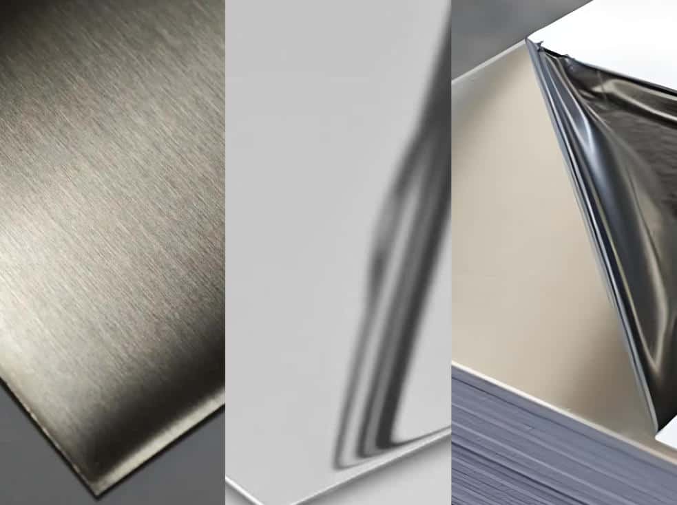
For high-surface-finish workpieces such as brushed sheets, mirror-finish sheets, and film-protected sheets (i.e., sheets with protective film), there are typically three core approaches to preventing scratches:
30-Second Quick Reference Chart
|
Surface types of sheets |
Common surface defects |
Preferred protection solutions |
Key precautions |
|---|---|---|---|
|
Brushed stainless steel |
Scratches, damaged grain pattern |
Urethane protective film, non-marking lower die with nylon inserts, roller-type non-marking lower die |
Avoid dragging along the grain; keep the tooling clean |
|
Mirror-finish stainless steel |
Indentations, drag marks, bright spots |
PU pad, non-marking lower die with polyurethane inserts, roller-type non-marking lower die |
Extremely sensitive to localized contact pressure and minute foreign particles |
|
Film-protected sheets |
Film damage, curled edges, creases |
Urethane protective film or PU protective pad, a lower die with a large radius or a larger shoulder radius |
The original film does not guarantee absolute safety; pay attention to localized pressure around holes and cut edges |
|
Painted/Pre-coated sheets |
Coating indentations, abrasions |
PU pad, non-marking lower die with nylon inserts |
Maintain as even a contact pressure as possible; avoid sharp contact |
|
Anodized aluminum |
Cracks in the oxide layer, scratches |
Polyurethane underlay or insert, roller-type non-marking lower die |
Avoid excessive bending, deformation, and sliding friction |
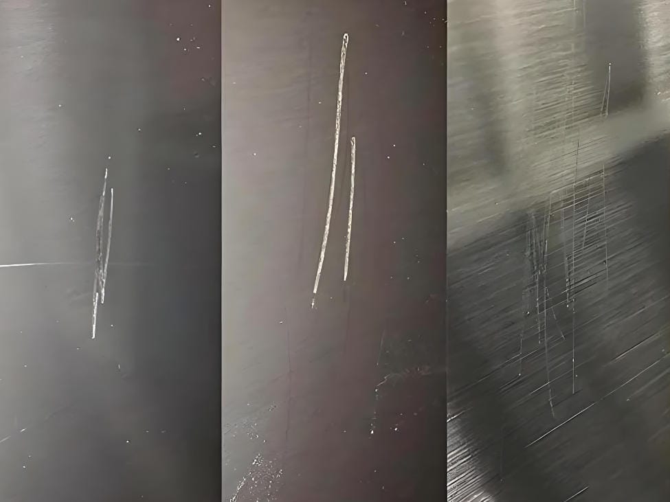
Why do your high-end sheets always get “marred” during bending? What constitutes true non-marking bending?
Why are workpieces with high surface finish requirements more prone to being scrapped than ordinary sheets?
Ordinary sheets generally do not have high surface finish requirements. During bending, minor friction or slight marks often do not affect delivery. However, workpieces with high surface finish requirements—such as brushed sheets, mirror-finished sheets, film-protected sheets, and coated sheets—are extremely sensitive to minor scratches, drag marks, and localized indentations. Even a single instance of damage can result in the entire sheet being scrapped. This is especially important in automotive sheet metal bending, where visible panels, protective covers, and small housings often require both appearance consistency and stable batch quality.
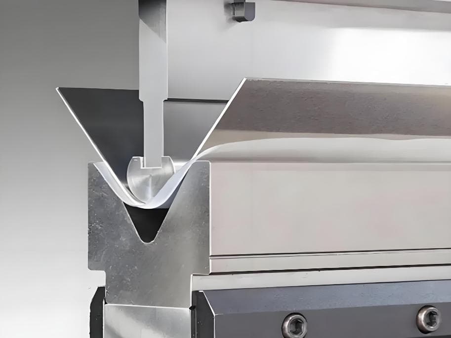
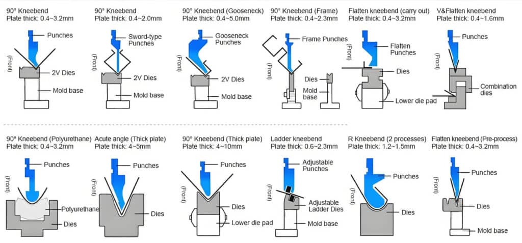
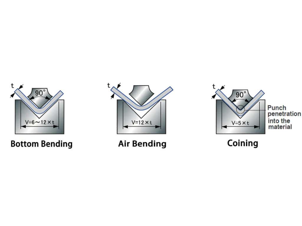
Why do traditional bending methods easily “damage the surface”?
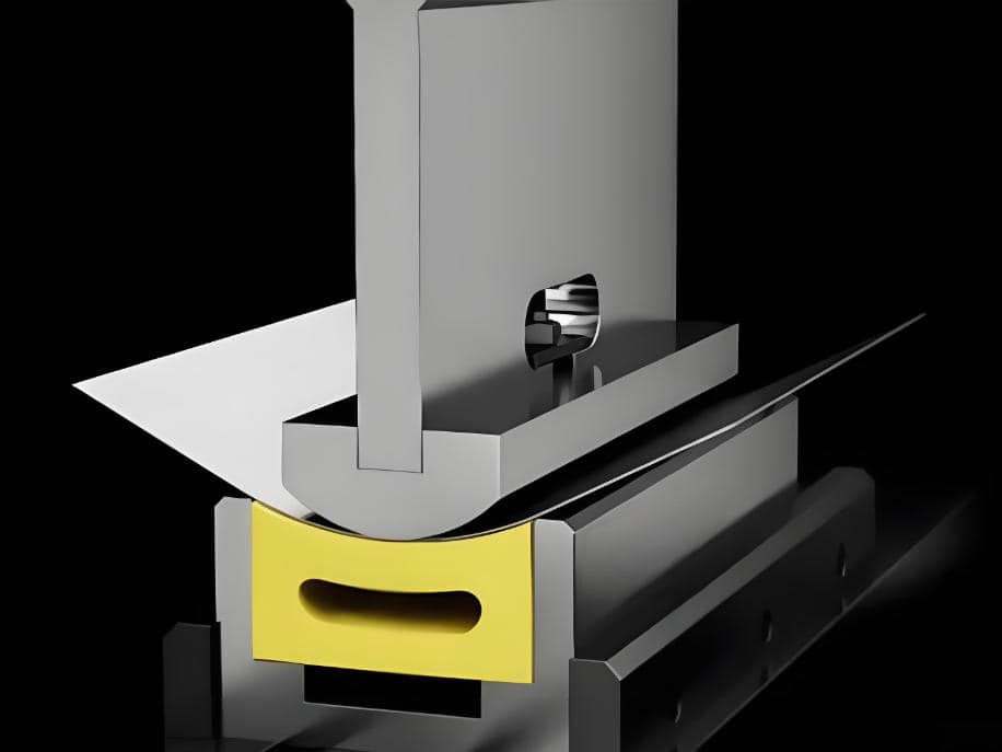
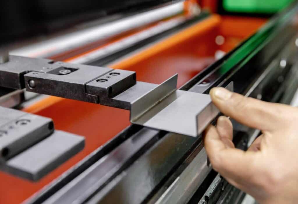
In common V-die air bending, as the sheet is pressed into the lower die, it typically undergoes relative movement against the two contact edges of the lower die, resulting in sliding friction. If these contact edges are too sharp or rough, or if localized stress on the sheet is excessive, the contact surface is prone to scratches, drag marks, indentations, or damage to the coating.
Workpieces most prone to issues
What constitutes true non-marking bending?
Non-marking bending does not imply “absolutely zero contact” between the metal sheet and the die. More accurately, it is a process objective aimed at minimizing surface damage to parts with high surface finish requirements. We can minimize surface damage by modifying contact methods, adding protective barriers, reducing sliding friction, and avoiding localized hard pressure, while also ensuring more stable equipment force application and bending operations. Ultimately, this achieves the process goal of “non-marking bending.”
Why isn’t non-marking bending simply a matter of purchasing a die?
Many factories believe that using a non-marking die alone will completely resolve surface issues on workpieces. However, in actual production, surface indentations and scratches are not caused solely by the die; unstable equipment, improper handling, and non-standard operating procedures can also lead to surface damage.
The ability to consistently achieve non-marking bending for parts with high surface finish requirements is often determined by a combination of contact methods, tooling cleanliness, operating procedures, and equipment stability—not by any single component.
Next, we need to understand exactly how these scratches and indentations are formed.
What causes scratches and indentations?
Sliding friction in the lower die contact area
When the sheet metal is pressed into the lower die, sliding friction typically occurs along the contact edges of the lower die. If these edges are too sharp or rough, scratches may form on the sheet metal surface during the friction process.
Indentations caused by localized overpressure
When the bending tonnage is too high, local pressure at the lower die contact edge is excessive, the punch tip radius is too small, or the press brake applies uneven force during bending, it can cause excessive localized stress on the sheet metal. This makes the sheet surface prone to indentations, which are more common on mirror-finished, film-protected, or soft-surfaced materials. Therefore, non-marking bending addresses not only scratches caused by friction but also indentations caused by localized overpressure.
Dirty tooling and microscopic foreign objects
A single tiny metal chip, scale, or burr residue on the tooling can easily be pressed into the sheet surface under high tonnage, forming dents or scratches. Many instances of surface damage may not result from incorrect process parameter settings, but rather from a dirty tooling surface or the presence of microscopic foreign objects.
Seams in segmented tooling, chipped edges, and worn areas
When tooling joints are uneven, there are height differences between segments of a segmented tooling, or the tooling has localized chipping, wear, or indentations, these can leave regular abrasion marks on the sheet surface.
Improper handling, turning, feeding, and support methods
In addition to surface damage caused during the bending process itself, many issues arise before loading the machine or after unloading.
For example:
Surface defects in workpieces with high surface finish requirements are rarely caused by a single factor; they are typically the result of a combination of contact methods, localized stress, the cleanliness of the contact interface, and handling practices.
Core solution 1: physical isolation—how to use protective layers, padding, and isolation media
This is the solution with the lowest barrier to entry and the fastest results.
This solution does not require replacing the entire tooling setup from the outset, making it well-suited for small-batch production or prototyping scenarios.
What are common protective media?
When to use each
Common issues during on-site use
Who is this solution best suited for?
This solution is best suited for scenarios involving small-batch, high-variety production; products in the prototyping phase; factories that have temporarily received orders with high surface finish requirements; or situations where one wishes to first verify the feasibility of scratch protection at a lower cost.
Core solution 2: die upgrades—when are true non-marking lower dies appropriate?
Why relying solely on protective film is often insufficient
When orders are repetitive, batch sizes are larger, and surface quality standards are stricter, relying solely on protective film is often not a very reliable solution.
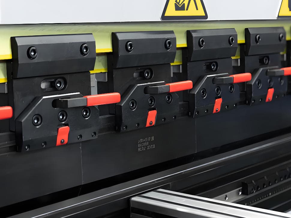
In this situation, we need to upgrade to a non-marking solution by switching to more stable and efficient dedicated non-marking dies. Before choosing a dedicated die, it is useful to review the basic logic of press brake tooling selection, including punch radius, V-die opening, insert materials, and lower die contact design.
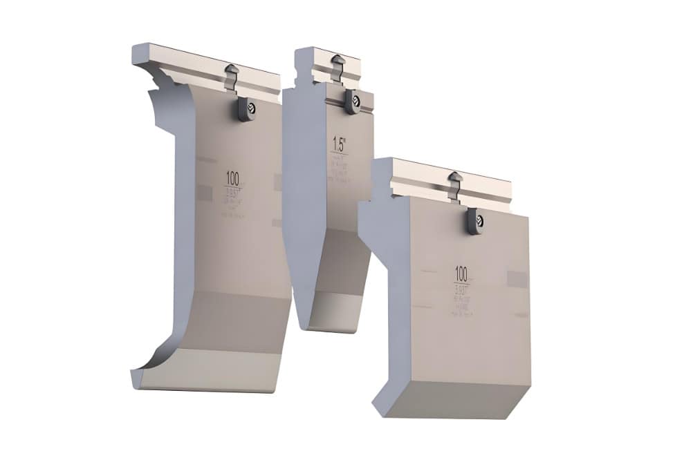
Non-marking lower dies with protective inserts
This is the most common type of non-marking lower die. The principle involves embedding a protective contact layer in the contact area of the lower die, which prevents direct, hard contact between the metal sheet and the lower die.
Advantages of this solution:
Limitations of this solution:
Rolling-contact non-marking lower die
Why is this solution more representative?
This is an advanced non-marking die solution that transforms the sliding friction between the sheet metal and the lower die edge into gentler rolling contact, greatly reducing frictional resistance. It is particularly suitable for appearance parts with high surface finish requirements, such as brushed, mirror-finished, or film-protected parts.
For which orders is it best suited?
It is suitable for orders with extremely high surface quality requirements, high-volume production, repeated manufacturing of similar parts, and a desire to minimize fluctuations caused by manual operations and the replacement of protective layers.
When should you upgrade from a “protective layer solution” to a “dedicated die solution”?
If your workshop exhibits any of these signs, it typically means you need to seriously consider upgrading to a dedicated die solution.
Core solution 3: equipment and production line capabilities
Why do localized indentations still occur even when using high-quality dies?
Even the best non-marking die cannot guarantee a flawless surface finish on the workpiece if the press brake itself lacks precision and stability. Inconsistent stress distribution in the middle of long workpieces and variations in repeatability can both compromise the effectiveness of the protective solution.
Why surface protection depends on equipment stability
Which equipment capabilities are more critical for high-appearance parts
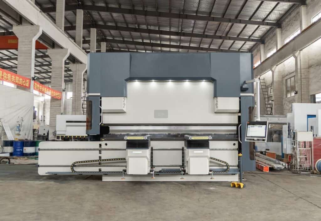
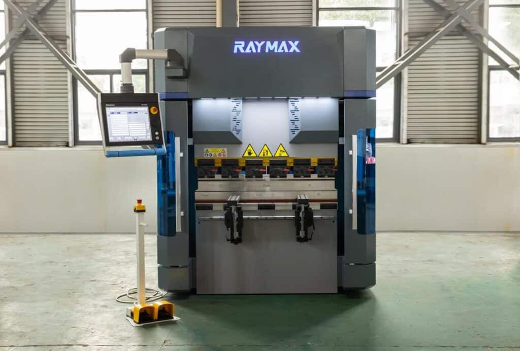
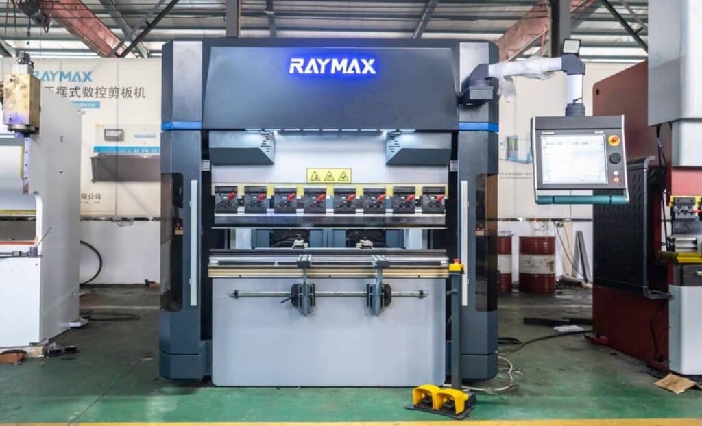
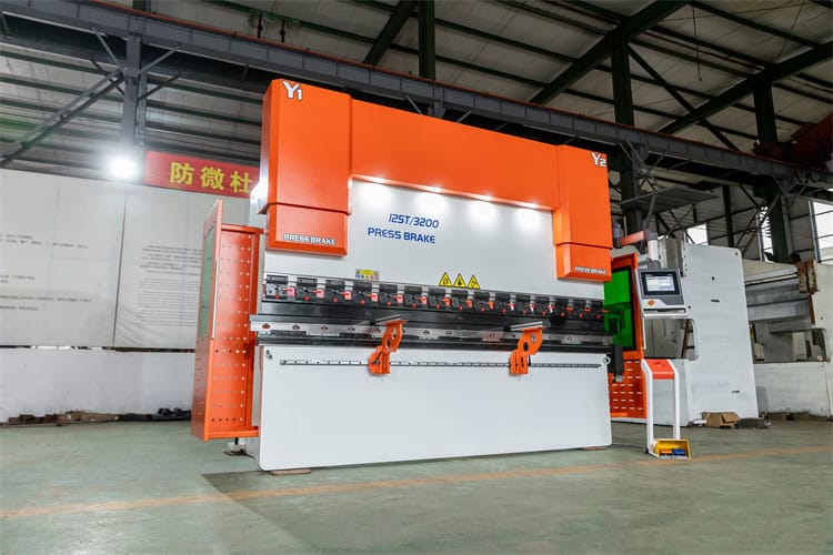
For factories that regularly process elevator door panels, kitchen cabinet panels, medical equipment housings, and high-end home appliance appearance parts, stable, non-marking bending requires a combination of high-precision press brake, suitable non-marking die, compensation systems, and standardized operating procedures. These appearance-sensitive parts are typical examples of common press brake applications, where forming accuracy, surface quality, and batch consistency must be controlled together.
In such applications, Raymax high-precision press brakes feature high repeatability, ensuring full-length consistency for long parts. They are compatible with a wide range of non-marking die, offering fast and stable tool changes that significantly boost production efficiency. If your production involves long-term sheet metal bending with high aesthetic requirements, it is essential to evaluate not only the non-marking die solution but also the press brake’s repeatability, compensation capabilities, support for long parts, and tool change stability. For such applications, the Raymax high-precision press brake can be considered as a viable option for evaluation.
Ready To Upgrade Your Metal Fabrication Line?
Email Us For A Free Consultation.
What are the specific challenges associated with workpieces of different surface types?
Brushed-finish workpieces
Mirror-finished workpieces
Film-protected sheets
Coated sheets, pre-coated sheets, and anodized workpieces
Summary: Different surface types present different bending risks. Brushed parts are more susceptible to scratches, mirror-finished parts are more prone to indentations, and film-protected parts require simultaneous control of both metal surface damage and film damage. Therefore, when selecting a non-marking solution, we must not only consider whether the workpiece has a factory-applied protective film but also take into account the workpiece type and production environment.
The invisible killer: overlooked details on the shop floor
Tooling Cleanliness Is Not Maintenance — It Is Process Control
Operator technique directly determines surface quality
Why long workpieces are more prone to surface defects
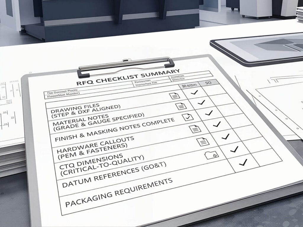
On-site scratch prevention checklist
Before bending parts with high surface finish requirements, we must check the following items:
Basic pitfalls to avoid: don’t let incorrect parameters undermine your efforts to prevent scratches
When performing non-marking bending, we often encounter a common problem: why do indentations still appear even when the protective measures are correct?
This usually happens because the bending load exceeds what the protective layer can tolerate. The main reasons are:
Achieving non-marking bending requires proper die opening, contact conditions, and force control.
How to choose the right solution? A single table clearly outlines workpiece types and production scenarios
When selecting a solution, we must make a comprehensive assessment based on order type, batch consistency, and production objectives.
|
Workpiece types |
Production status |
Most common issues |
Recommended solutions |
Why it’s suitable |
Production considerations |
|---|---|---|---|---|---|
|
Brushed stainless steel |
Small-batch prototyping |
Scratches and minor marks on the textured surface |
Urethane protective film / PU pad |
Low investment, flexible changeovers |
Carefully inspect the tooling cleanliness, the bending action, and the contact areas for metal shavings |
|
Brushed stainless steel |
Repeat orders |
Regular scratches appearing in batches, with inconsistent quality |
Non-marking lower dies with protective inserts |
More stable than temporary protective film |
Pay attention to the wear of the insert and the condition of the contact areas |
|
Brushed stainless steel |
Long-term bulk production |
High scrap costs |
Roller-type non-marking die solution + high-precision press brake |
Better suited for high-standard, long-term operations |
Evaluate the equipment’s repeatability, compensation, and support capabilities |
|
Mirror-finished stainless steel |
Small to medium-batch production |
Spot indentations, scratches, and localized marks are significantly magnified |
non-marking lower die with polyurethane or nylon inserts |
Higher requirements for surface uniformity |
For the first piece, focus on the reflective surface and localized indentations |
|
Long-term bulk production |
High batch consistency requirements; localized overpressure can easily result in the entire batch being scrapped |
Roller-type non-marking lower dies |
Better suited for long-term batch production and scenarios with high aesthetic requirements |
Pay close attention to compensation consistency, repeatability, and support for long parts |
Pay close attention to compensation consistency, repeatability, and support for long parts |
|
Film-protected sheets |
Occasional processing |
Film damage, curled edges, and localized indentations |
Urethane protective film / PU pad |
Low cost, suitable for initial trial production |
The fact that the sheet metal comes with a factory-applied protective film does not mean it will not be damaged during bending |
|
Film-protected sheets |
Consistently unstable yield rates |
Simultaneous damage to the metal surface and factory protective film, resulting in significant batch-to-batch variation |
Insert-type or roller-type non-marking die solution |
More stable than temporary protective layers |
Focus on inspecting hole edges, notches, short flanges, and areas subject to localized high pressure |
|
Painted sheets / Pre-coated sheets |
Routine production |
Surface indentations and edge abrasions |
Protective layer solution or non-marking lower die with polyurethane or nylon inserts |
Reduces surface damage caused by hard contact |
Pay attention to edge scuffing and protection of the backgauge contact points |
|
Anodized aluminum parts |
Routine production |
Surface prone to scratching, with visible indentations |
Protective layer solution |
Sensitive surface requiring gentler handling |
Ensure surface cleanliness, stable support, and proper workpiece handling methods |
|
Anodized aluminum parts |
Frequent prototyping, unstable order volume |
Difficulty standardizing tooling and protective solutions |
Urethane protective film / PU pad |
High flexibility, suitable for switching between multiple product varieties |
Consistency is typically inferior to dedicated die solutions |
|
Anodized aluminum parts |
Repeated production of small to medium-batch appearance parts |
Minor issues with individual pieces, but scratches appear in batches |
non-marking lower die with polyurethane or nylon inserts |
Balances stability and cost |
Establish a system for mandatory first-piece inspections and regular replacement of consumables |
|
Long appearance parts |
Prominent surface defects |
Localized indentations in the center, drag marks along the long edges, and poor consistency along the entire length |
Non-marking dies + CNC sheet followers + compensation system |
Issues with long parts are often not just a tooling problem |
Pay close attention to support for long parts, full-length stress distribution, and the operating path |
For a practical application example involving long appearance parts, see our guide to non-marking bending for elevator panels.
Summary:
Conclusion
To achieve consistent, non-marking bending, several factors must be taken into account, including tooling selection, protective media, equipment precision, on-site management, and operating procedures.
If you are struggling with bending parts that have high surface finish requirements, please send us your part drawings, material specifications, thickness, and surface finish requirements. Raymax’s engineering team can provide customized CNC press brake solutions for appearance parts and a tailored quotation, covering everything from tooling selection to machine configuration.
Ready To Upgrade Your Metal Fabrication Line?
Email Us For A Free Consultation.
Frequently Asked Questions (FAQs)
Related Blog
a guide to 11 Types of press brake bending process
Press Brake Tooling Guide: Punches, Dies, Types and Selection
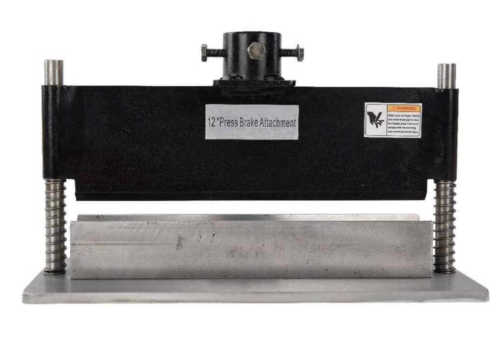
Press Brake Attachment Guide (2026): Types, Uses, Tooling & Quick-Change Systems
-1024x768.jpg)
How to Improve Press Brake Bending Consistency: Causes, Checks & Solutions
What is a Press Brake Operator? Duties, Skills, Salary & Career Prospects Explained!
One-Stop Guide to Hydraulic Press Brake: Working Principle, Bending Process & Applications
The Heart of Every Press Brake: Select, Maintenance & Upgrade Hydraulic Cylinders
Press Brake Radius Mastery: Inside/Outside Radius, 8× Rule, and Real-World Tips
Air Bending vs Bottom Bending vs Coining: Which Press Brake Bending Method Is Right for You?
Definition of press brake tool material
Press Brake Quick Clamping System: Types, Compatibility & How to Choose (Quick Clamp Guide)
Press Brake Overview and Smart Selection Tips
Post Your Review
Share Your Thoughts And Feelings With Others
7 responses to “Non-Marking Press Brake Bending: How to Prevent Scratches on Brushed, Mirror-Finish & Film-Protected Sheets”
This is my first time pay a quick visit at here and i am really happy to read everthing at one place
I appreciate you sharing this blog post. Thanks Again. Cool.
There is definately a lot to find out about this subject. I like all the points you made
Makaleniz açıklayıcı yararlı anlaşılır olmuş ellerinize sağlık
I do not even understand how I ended up here, but I assumed this publish used to be great
Ne zamandır web sitelerim için aradığım içeriği sonunda buldum. Bu kadar detaylı ve net açıklama için teşekkürler.
I really like reading through a post that can make men and women think. Also, thank you for allowing me to comment!