
Francis Pan
Francis Pan is the Foreign Trade Manager of RAYMAX, with over 10 years of experience in sheet metal fabrication equipment and CNC machinery. He has worked closely with manufacturers worldwide on press brakes, fiber laser cutting machines, fiber laser welding machines, and practical production-oriented metal processing solutions.
Top Guidelines
-1024x768.jpg)
-1024x768.jpg)
-1024x768.jpg)
-1-1024x768.jpg)
Table Of Contents
Stay in the the loop
Subscribe To Our Newsletter
Key takeaways
The most common issues with bending electrical enclosures are not typically whether the parts can be bent to a 90° angle, but rather the following three points:
For parts with multiple bends, multiple holes, and complex assembly relationships, the key to finished product quality lies not only in the accuracy of individual angles but also in the following factors:
Therefore, when performing bending operations for electrical enclosures, we must pay attention to the following points:
This article will systematically analyze the causes of common issues in electrical enclosure bending—covering key aspects such as flat-pattern calculation, flange accuracy, assembly fit-up, long-edge consistency, and bending sequence—and teach you how to proactively manage these issues.
“30-Second Quick Reference Chart” for common electrical enclosure bending issues:
|
Observed issues |
Most likely causes |
Priority check items |
|---|---|---|
|
The side panel can be bent, but it still does not line up with the other panels during assembly. |
Incorrect flat-pattern parameters; insufficient clearance at corners |
Flat pattern calculation, corner clearance |
|
The first piece in a batch passes inspection, but subsequent units begin to exhibit dimensional deviations. |
Unstable repeatability; material variation |
Back gauge repeatability, sampling of consecutive parts |
|
After installation, the door panel’s four corners are misaligned. |
Diagonal dimensions out of tolerance; inconsistent angles on long sides |
Bending sequence, back gauge repeatability, consistency of long-edge angles |
|
The final bend cannot be made, or the part collides with the tooling after bending. |
Incorrect bending sequence causing interference |
Offline 3D simulation, or re-planning of the bending sequence |
|
Hole positions become distorted, elongated, or misaligned with mating parts after bending. |
Holes too close to the bend line |
Distance from hole edges to bend lines on the drawing |
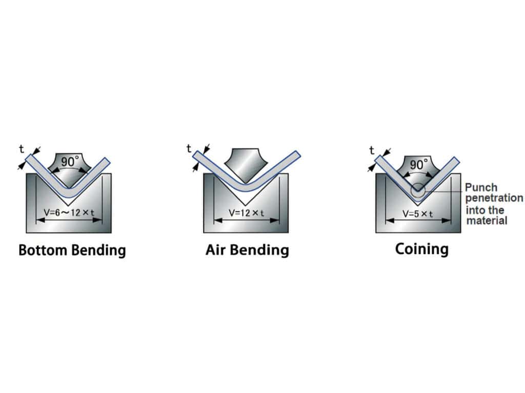
(Note: The parameters and experience ranges in this guide apply to air bending.)
Why are bends in electrical enclosures more prone to problems than standard bent parts?
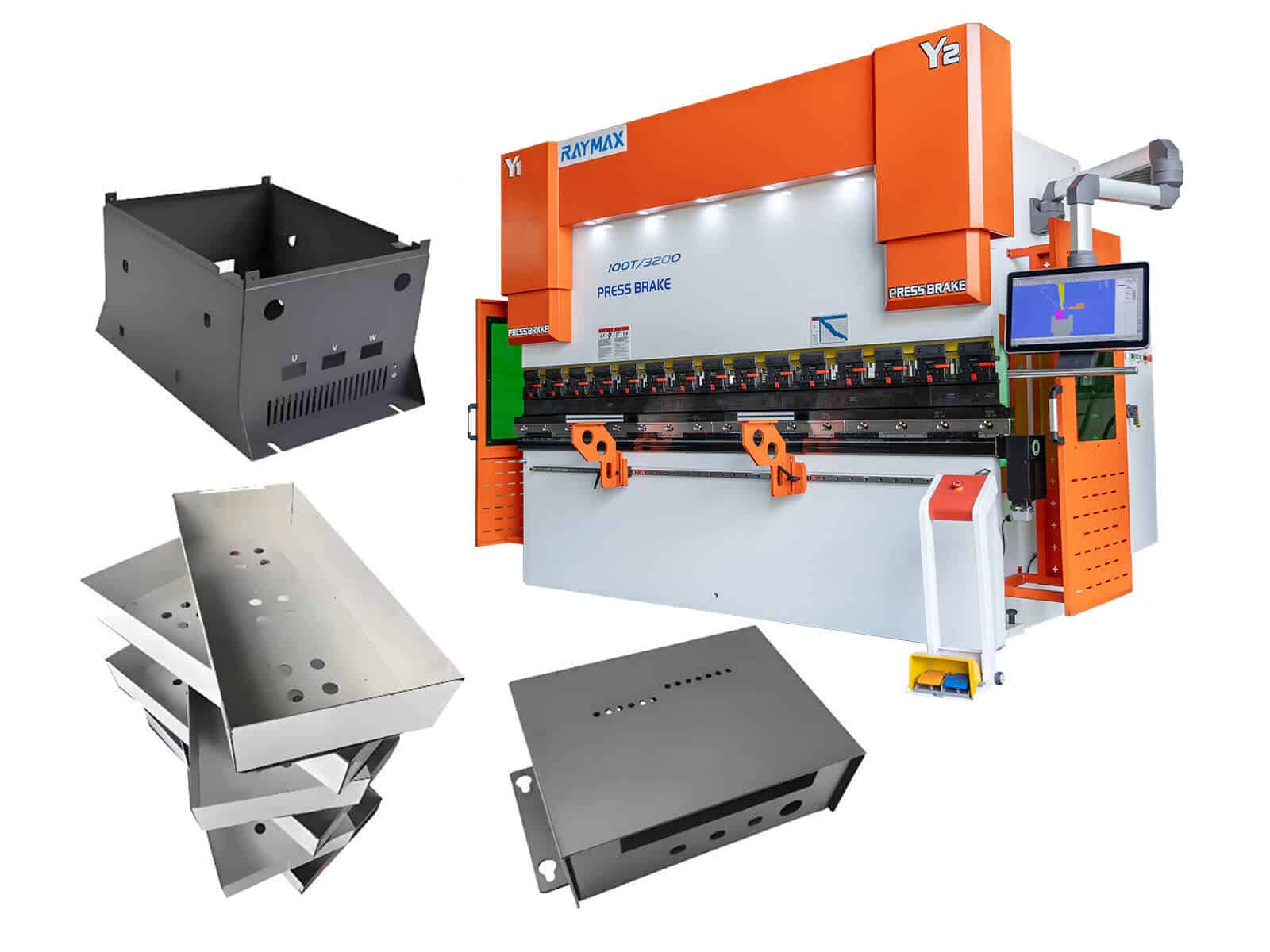
Standard bent parts typically have only one or two bends, requiring focus primarily on the bending angle and a single dimension. However, parts such as electrical enclosures, control cabinet doors, equipment enclosures, and distribution boxes often require multiple bends and feature numerous holes, and must also account for subsequent assembly relationships. If you are still comparing general bending use cases, you can first review the common press brake applications and bend types before evaluating enclosure-specific bending risks.
Our requirements for these parts go beyond simply “being able to bend them”; we must also ensure that after bending, the workpiece can be assembled smoothly, with even door gaps, properly aligned holes, and a square overall shape.
Bending electrical enclosures is more prone to issues because dimensional errors tend to accumulate. For example, a 0.3mm error on a single edge may seem minor, but after multiple edges, repeated flipping of the part, and repeated positioning, this small error is amplified. This can eventually lead to warped door panels, uneven joints between top and bottom panels, mounting plates that do not fit, and misaligned holes.
Therefore, when bending electrical enclosures, we must not only control specific angles but also consider the following aspects:
Thus, for components like electrical enclosures, simply achieving the bent shape is far from sufficient; our ultimate goal is to ensure they can be installed smoothly and properly.
Flat pattern calculation: the first foundation for accurate enclosure dimensions
Many enclosure bending problems seem to appear during bending or assembly, but they often start in the flat-pattern stage. The most typical scenario is this: the CAD model appears flawless, and the flat pattern is automatically calculated and generated, yet when the first piece is bent, the overall dimensions turn out to be too long or too short.
Flat-pattern dimensions are influenced by multiple factors, including material type, sheet thickness, inside radius, V-die opening, bending methods, and target formed states; conversely, material springback and actual forming angles affect the calibration results of BA, BD, and K-factor.
Therefore, flat-pattern calculations cannot simply rely on the software’s default parameters; these should only serve as a starting point for modeling. This is particularly true for complex, multi-sided parts like electrical enclosures, where even a slight error in the flat-pattern parameters can lead to significant differences in the actual formed state.
Below are several key principles for flat-pattern calculation:
1. Flat-pattern dimensions are not the result of mechanically plugging values into a fixed formula.
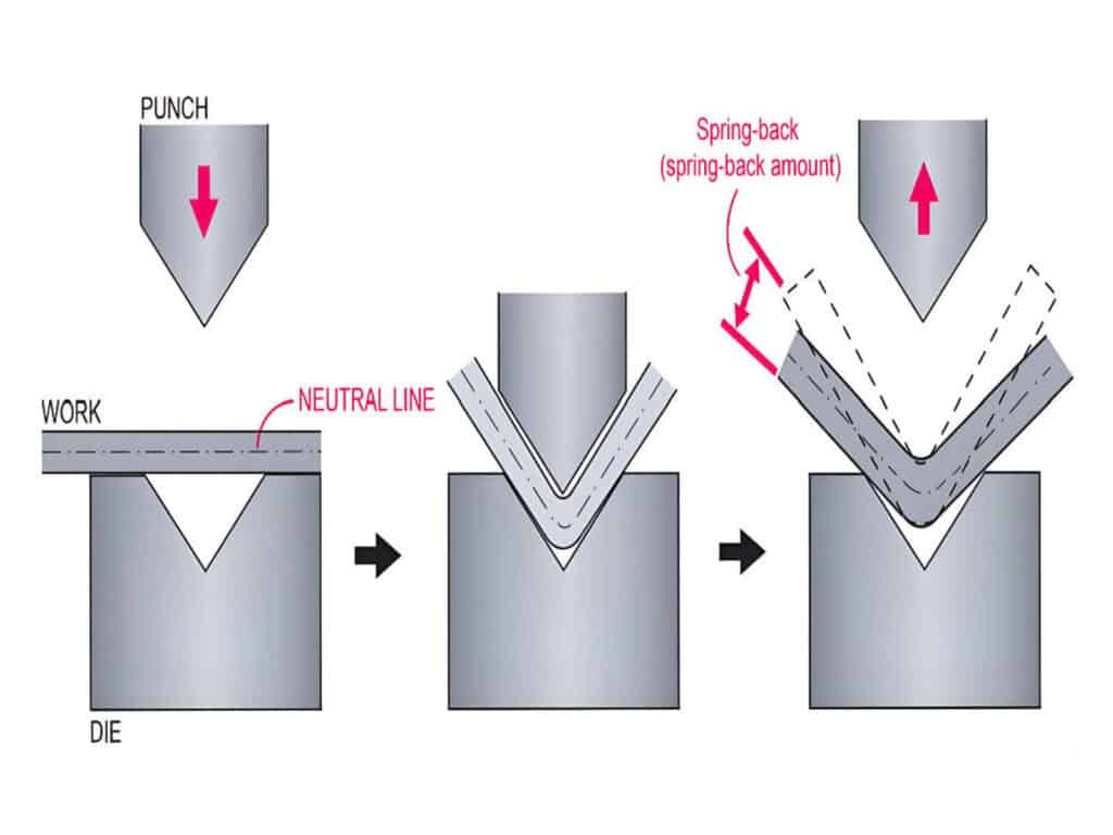
When the sheet is pressed into the lower die, the material on the outer side is stretched, while the material on the inner side is compressed. Between the stretching and compression zones lies a region where neither significant stretching nor compression occurs; we refer to this as the neutral axis. In flat-pattern calculation, the key is to determine the position of the neutral axis.
Different materials—such as low-carbon steel, stainless steel, and aluminum sheet—have varying ductility and yield strengths even when their thicknesses are identical. Furthermore, the position of the neutral axis will vary depending on the V-die and inside radius conditions. Therefore, we cannot rely entirely on a single set of default parameters for calculations.
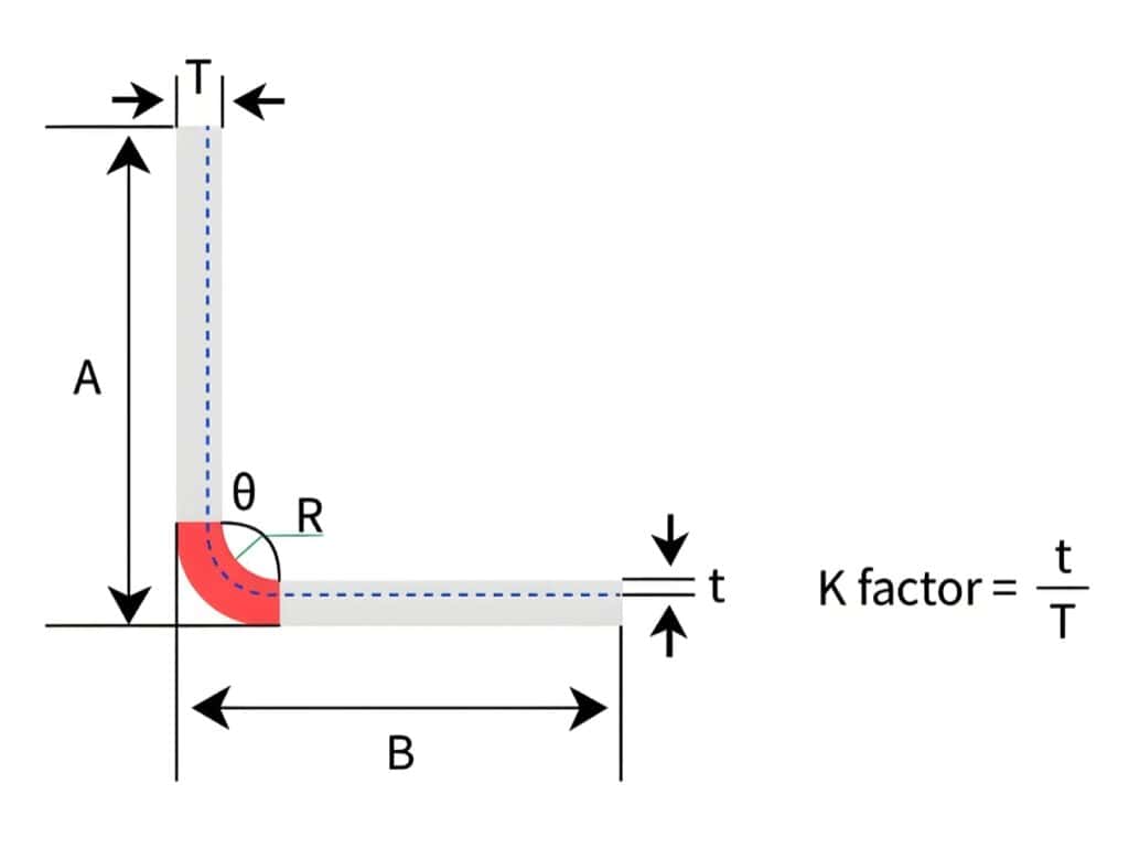
2. The default K-factor does not equal your actual K-factor.
The default K-factor in the software is merely an empirical starting point for preliminary estimates. For mass-produced enclosure components, it is recommended to determine the flat-pattern parameters based on actual test bending data from the same material, thickness, and tooling combination, rather than relying on arbitrary guesses based on experience.
3. Enclosure components are particularly sensitive to inaccurate flat-pattern parameters.
Since enclosure components typically involve multiple flanges and complex assembly relationships, even a slight deviation in the calculation of flat-pattern dimensions can lead to numerous subsequent issues, such as incorrect overall width or height, uneven door panel overlap, mounting plates that won’t fit, or misaligned hole positions.
The correct process for calculating flat patterns is typically as follows:
Therefore, for electrical enclosure bending, errors in flat pattern calculations are not minor discrepancies but the root cause of flange misalignment, hole position shifts, and subsequent assembly failures.
Flange precision and dimensional consistency: why batch consistency is more important than first-piece accuracy
When many enclosure components are installed on-site, the issues that arise are often not due to incorrect angles, but rather to inconsistent flange dimensions.
For example: If the left flange of a single part measures 50 mm and the right flange measures 50.5 mm, the difference may seem negligible. However, during the on-site assembly phase, problems such as gaps, misalignment, large weld seams, and crooked door panels will become apparent.
Common causes of flange dimensional drift include: inaccurate repeatability of the back gauge, inconsistent operational reference points, cumulative errors from repeated part flipping, material springback variations, and inconsistent program compensation. For multi-sided enclosure components, these issues rarely exist in isolation; instead, they interact with one another and are ultimately magnified during assembly.
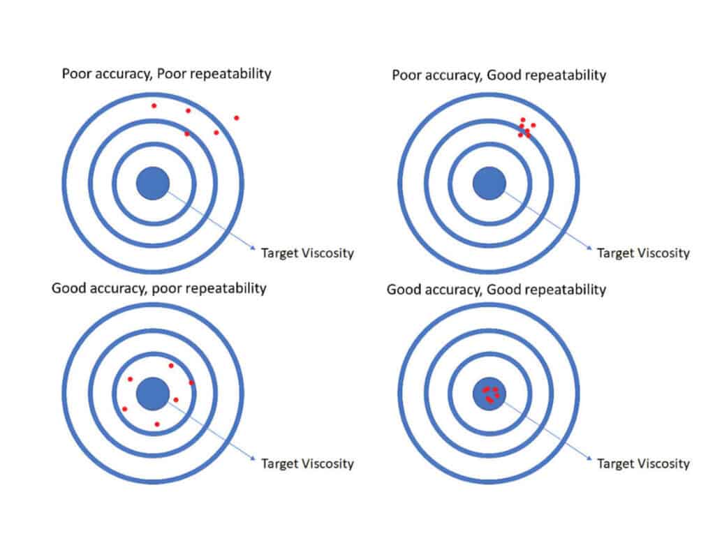
Why repeatability is more important than accuracy
For batch production of enclosure components involving multiple bends, repeatability is more critical than accuracy. This is because in batch production, the greatest concern is not that the first piece meets dimensional requirements, but that dimensions begin to drift during continuous production.
However, flange drift is not necessarily solely due to back gauge positioning issues. Even when using the same program, materials from different batches may have varying strengths and springback characteristics, which can also affect flange dimensions. Therefore, controlling flange dimensional consistency requires not only the back gauge repeatability but also springback control and test bending.
Recommendation to include inspection steps
When verifying flange accuracy and dimensional consistency, we should not limit testing to the first piece. A more practical approach is to randomly inspect the 1st, 10th, and 50th pieces to ensure that critical flange dimensions remain stable. For edges that significantly impact assembly, we recommend establishing a fixed sampling schedule.
Therefore, for enclosure components, true value lies not in the first piece passing inspection, but in the ability to continuously produce a batch of workpieces with stable flange dimensions.
Assembly misalignment issues: why parts that have already been bent still won’t fit during assembly
During on-site assembly, we often encounter various problems, such as edges not aligning, misaligned holes, uneven door gaps, and top and bottom panels that won’t fit together.
These issues are typically not caused by the installation method itself, but rather by deficiencies in the prior flat-pattern calculations, process allowances, bending sequence, and positioning control.
Actual Formed Corner Radius Not Considered
Bent corners are not mathematically sharp angles but have actual radii. If mating parts are designed with a “straight-to-straight” approach, the parts will collide with each other at the bent corners during on-site assembly. This situation is common when installing door panels, mounting plates, internal supports, and inner frames.
Holes, slots, and openings are too close to the bend line
Areas near the bend line experience stretching and compression during the forming process. Therefore, if hole positions are too close to the bend line, deformation, displacement, or elongation into an elliptical shape may occur, thereby affecting the installation of fasteners.
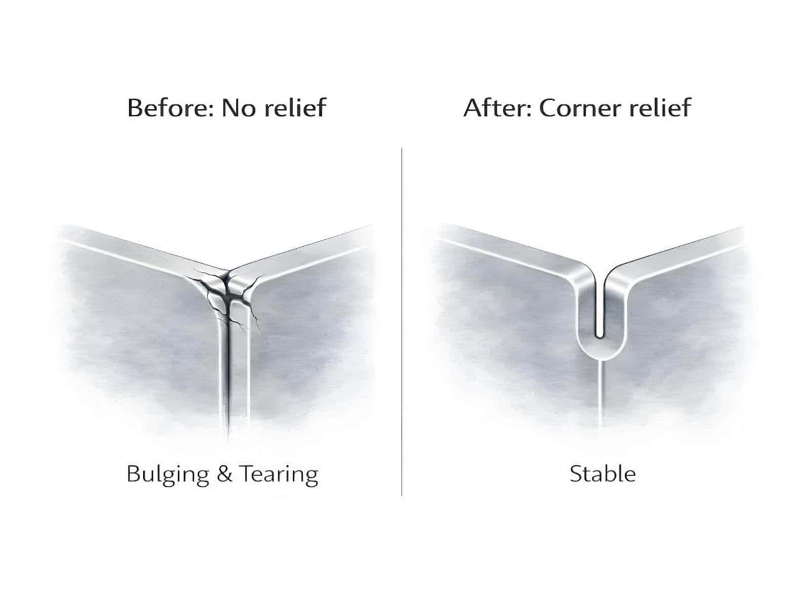
Improper bend relief or corner relief design
Reasonable bend relief or corner relief is often required at the four corners of the enclosure and at cross-flanges. Without adequate clearance, material at the corners may experience material crowding, tearing, or bulging; in severe cases, forming may even be impossible.
Individual dimensions pass inspection, but assembly alignment is off
A common phenomenon in enclosure component bending is that while each individual edge may measure within specifications, the enclosure assembly appears skewed when assembled. This is because many assembly issues with enclosure components stem not from individual edge dimensions, but from the relative positional relationships after multiple bends, the accumulation of tolerances, and issues with reference point transitions. This typically indicates that the problem lies not in a single dimension, but rather in excessive reference point transitions, excessive cumulative errors across multiple edges, and uncontrolled relative positional relationships.
Many assembly issues encountered on-site are not fundamentally due to incorrect operating procedures, but rather the combined result of errors in structural design, flat-pattern calculations, positioning control, bending processes, and compensation.
Squareness, perpendicularity, and angular consistency along the entire length of long enclosure components
For cabinet doors, side panels, and long enclosure components, what truly affects the visual appearance and fit of the assembly is often not a deviation in a single angle, but rather the consistency of the angles along the entire length of the edge. If the angles on the left, center, and right sides are inconsistent, this may result in warping or distortion during installation.
Common misconceptions regarding long components
Many people, when measuring long door panels or side panels, habitually measure only the angle at the center. This approach is insufficient for long enclosure components. The issue with long workpieces often lies in the fact that while the center angle may be accurate, the angles at both ends are either too large or too small
Under what conditions is full-length inconsistency more likely to occur
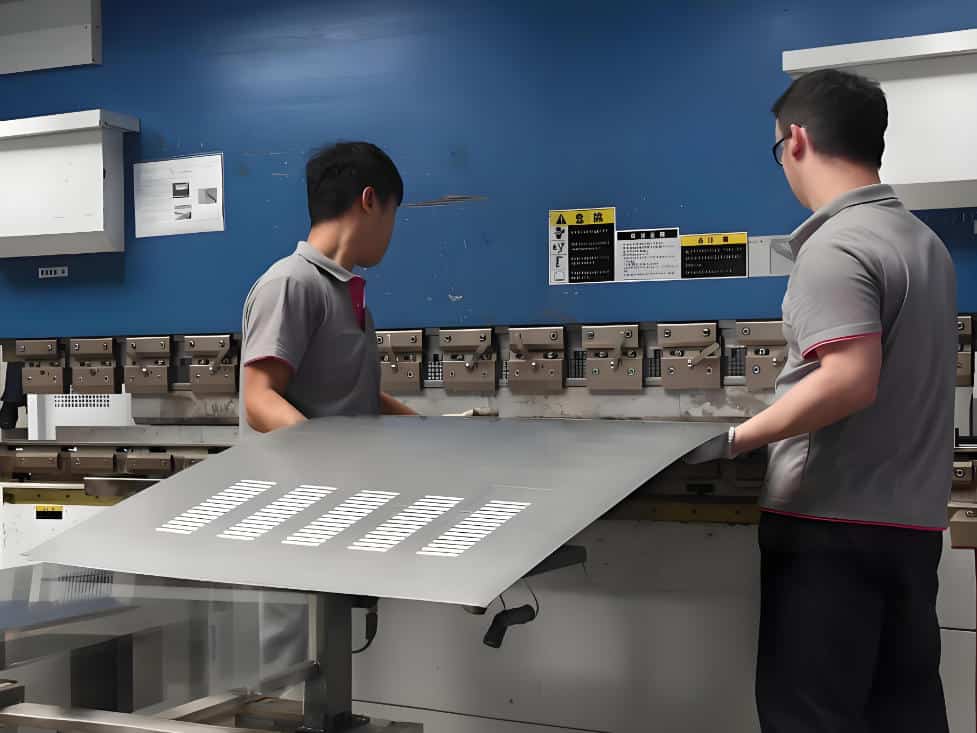
Long workpieces, thin sheets, stainless steel or other high-resilience materials, door panels with protective film or high surface finish requirements, and workpieces whose length approaches the press brake’s effective bending length are more prone to full-length inconsistency issues. For these surface-sensitive enclosure parts, non-marking bending for protective-film and high-surface-finish sheets should also be considered together with angle consistency, crowning, and sheet support.
Why do left, center, and right angles vary?
The longer the workpiece, the less reliable it is to rely solely on the center point angle. When bending long workpieces, the ram and table undergo deflection under load. Without crowning, the angles at the center and ends of the workpiece may not match.
Why is crowning especially important for enclosure components?
Enclosure components generally have high requirements for full-length angle consistency, uniform door gaps, and squareness. Crowning helps correct longitudinal deflection in the press brake and tooling during bending, thereby reducing the angle difference between the center and the ends of long workpieces and improving full-length angle consistency. Therefore, crowning is particularly important for enclosure components.
Why do sheet followers or sheet followers also affect stability?
When bending long, thin door panels or side panels, we typically use sheet followers to stabilize the workpiece and ensure a stable bending process. However, if the support method is incorrect, the workpiece may sag or sway, affecting the bending angle. Even if the program and compensation settings are correct, this can still compromise the final forming result.
Inspection recommendations
For long-edge enclosure components, measuring only the angle at the center is insufficient; it is essential to check the angles at the left, center, and right points, while also verifying that the lengths of the two diagonals are consistent. After confirming that the angles and lengths are correct, a final test assembly should be performed to ensure that the gaps in the door panels are uniform. For machine acceptance or batch-production verification, you can also use a press brake bending accuracy checklist for angle, flange length, and straightness to standardize the inspection process before mass production.
The real challenge in bending enclosure components lies not in the deviation of a single angle, but in the lack of consistency across the entire edge, the entire frame, and the entire door panel during assembly.
The final step that determines success or failure: enclosure bending sequence
Many enclosure components appear normal during the earlier stages of production, but problems often come to light during the final process: for example, workpieces getting stuck in the lower die and unable to be removed, already bent edges colliding with the tooling, the upper punch failing to close, insufficient space for flipping the workpiece, or the risk of collisions during the final process. These issues are not necessarily caused by programming errors; they are more likely due to an incorrect bending sequence.
The bending sequence determines three key factors:
For complex enclosure components, relying on on-site judgment to determine the bending sequence often makes it difficult to ensure stability and accuracy. There is no fixed formula for the bending sequence of complex enclosure components; the priority principles should be:
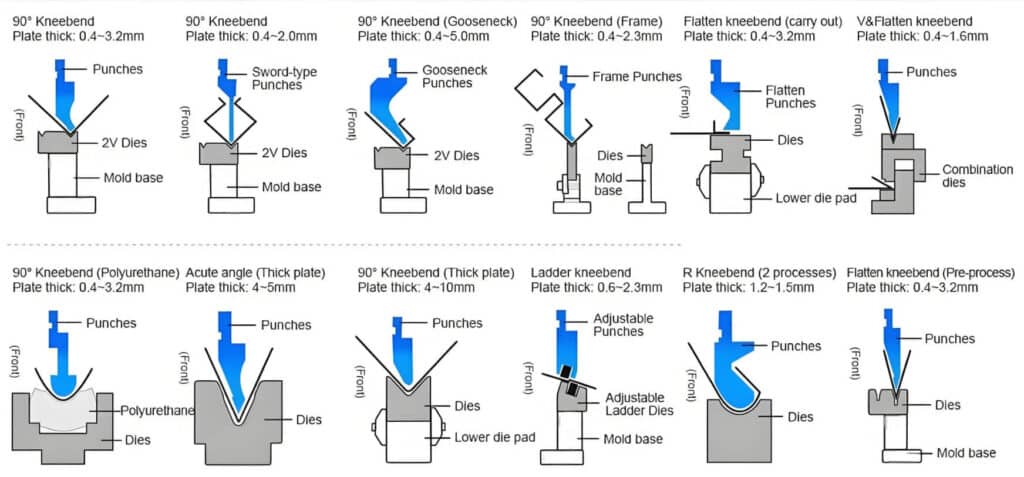
In many designs, we typically prioritize bending short edges and inner edges first; however, the final sequence must still be determined based on part geometry, tooling clearance, and offline simulation results. To provide clearance for previously bent edges, we may also need to use a gooseneck punch or sectional tooling.
The more complex the enclosure component, the more essential it is to perform bend path simulations and interference checks using 3D offline software before bending. Compared to trial-and-error testing with steel sheets on-site, early simulation is far more effective at saving material and time. If your enclosure parts involve asymmetric shapes, multiple positioning references, deep flanges, or frequent program changeovers, a 6-axis press brake for complex enclosure bending can help reduce manual repositioning and improve repeatability.
Many enclosure parts are not impossible to bend; rather, problems arise because the bending sequence is incorrect, causing issues to surface only during the final processing step.
Six critical process guidelines for enclosure bending
Do not neglect the minimum flange length
If the flange is too short, the workpiece may not be able to form a stable support on the lower die, resulting in dimensional instability or even failure to form properly.
As a rule of thumb, we typically use ≥4T as the minimum flange length. However, the final minimum flange length must be determined based on the V-die opening of the lower die, the material, and the tooling conditions.
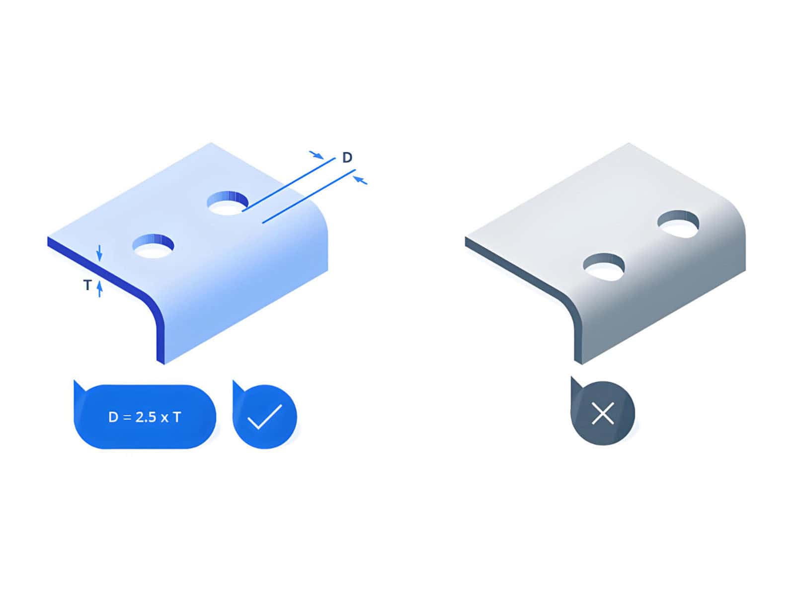
Do not place holes and slots too close to the bending line
When features such as holes, slots, and notches are too close to the bending line, they are prone to deformation and misalignment, which can affect subsequent assembly.
As a rule of thumb, we generally use ≥4T as the minimum distance between holes/slots and the bending line. However, for applications requiring high assembly precision, this must be verified in conjunction with the material, sheet thickness, and inside radius.
Bend Relief and Corner Relief at Box Corners and Cross-Flanges
Reasonable bend relief or corner relief must be provided at the four corners of a box and at cross-flanges; otherwise, the corners are prone to bulging, material extrusion, tearing, and interference.
As a rule of thumb, we typically use ≥50% of the sheet thickness as the starting point for the relief width, and the inside radius + sheet thickness + 0.020 inches (approx. 0.5 mm) as the starting point for the relief depth. Actual values must be adjusted based on specific operating conditions.
Mating parts should not interfere with the actual formed bend radius zone
After bending, the corners have a real radius. Mating parts should not be designed based on the assumption of a mathematical sharp corner, as this may cause them to abut against each other in the bend radius area.
For mating structures such as door panels, mounting plates, and internal support members, we should strive to position them away from the actual formed bend radius.
Do not evaluate long-edge parts based on a single point angle
For long-edge parts, a 90° angle measured at the center does not guarantee consistency along the entire edge.
What truly affects door gaps and squareness is often the full-length consistency at the left, center, and right points.
Review sequence and reference points for multi-bend structures in advance
Before manufacturing complex enclosure components, perform bend path simulations and interference checks in advance. If the bending sequence is incorrect, cumulative dimensional errors and interference issues often become concentrated and exposed during the final processing step.
For complex enclosure components, we recommend conducting a sequence review in advance and, if necessary, performing offline simulation tests first.
Troubleshooting process for enclosure fit-up issues
Step 1: verify the flat pattern parameters
Check whether the sheet thickness, inside radius, bend allowance, and target angles are correct, and verify that the parameters have been calibrated using test-bent samples. Many issues stem from incorrect calculations in the flat pattern drawings.
Step 2: check flange length, not just angles
Verify that the batch dimensions of critical flange edges are consistent, rather than focusing solely on angles. Mismatched enclosure edges during assembly are often due to fluctuations in flange dimensions.
Step 3: check the relationship between hole locations and bend lines
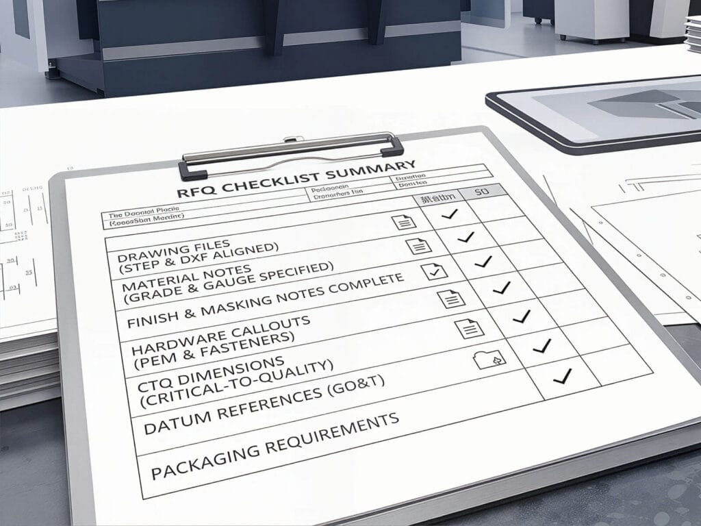
Check whether holes near bend lines have become distorted or if their relative positions have shifted. Pay particular attention to screw holes, PEM fastener holes, viewing ports, and interface openings, as these are more likely to reveal issues after bending.
Step 4: inspect clearances and corners
Verify that adequate corner clearances have been provided and check for issues such as material crowding, bulging, tearing, or local interference.
Step 5: Review the bending sequence
Check whether the final bend is prone to interference, whether cumulative errors have occurred due to frequent changes in the reference plane, and whether issues such as bent edges contacting the tooling or unreasonable flipping have arisen.
Step 6: Perform a test assembly, do not limit yourself to dimensional verification
After test-assembling the door panel, mounting plate, fasteners, and mating parts, check the gaps, squareness, and overall fit.
Conclusion
High-quality bending of electrical enclosures requires more than just accurate angles; it depends on the consistent performance of flat-pattern calculation, flange consistency, squareness, bending sequence, and full-length angle consistency during batch production. For components such as control cabinets, distribution boxes, equipment enclosures, and door panels, the sustained stability of the entire process and equipment capabilities is more important than the results of a single test bend.
If your factory is experiencing difficulties with enclosure assembly, significant dimensional variations, uneven door gaps, or inconsistent angles along the entire length, relying solely on repeated trial bends and on-site adjustments usually fails to resolve the issues at their root. Instead, you need to examine the flat-pattern parameters, bending sequence, positioning repeatability, and the equipment’s compensation capabilities for processing long workpieces.
If you need to manufacture enclosure components or are encountering issues in the manufacturing process, please feel free to send us your drawings, material types, sheet thickness, maximum bending length, and surface finish requirements. Raymax will assess the feasibility of bending your enclosure components, identify key process risks, and propose press brake solutions for electrical enclosure bending.
Ready To Upgrade Your Metal Fabrication Line?
Email Us For A Free Consultation.
Frequently Asked Questions (FAQs)
Related Blog
What is a 6 Axis Press Brake? Working Principles, Advantages, Applications, and Buying Guide
Press Brake Repeatability vs Accuracy: Definitions, Test Methods & Common Misunderstandings
Air Bending vs Bottom Bending vs Coining: Which Press Brake Bending Method Is Right for You?
-1024x768.jpg)
How to Improve Press Brake Bending Consistency: Causes, Checks & Solutions
Press Brake Bending Accuracy Checklist: 10 Quantified Factors to Inspect
Press Brake Tooling Guide: Punches, Dies, Types and Selection
How to Reduce Springback in Press Brake Bending (SS/AL/MS Checklist)
Bend Allowance vs Bend Deduction vs K-Factor: How to Calculate Sheet Metal Flat Patterns (With Examples)
How to Use a Press Brake Machine for Precise Bending
Press Brake for Stainless Steel: Tonnage, V-Die Selection, Springback & Surface Protection
-1024x768.jpg)
How to Measure Press Brake Bending Angle: Tools, Methods & Calibration Pitfalls
Press Brake Air Bending: Guide to Principles, Calculations & Best Practices
Post Your Review
Share Your Thoughts And Feelings With Others