
Francis Pan
Francis Pan is the Foreign Trade Manager of RAYMAX, with over 10 years of experience in sheet metal fabrication equipment and CNC machinery. He has worked closely with manufacturers worldwide on press brakes, fiber laser cutting machines, fiber laser welding machines, and practical production-oriented metal processing solutions.
Top Guidelines
-1024x768.jpg)
-1024x768.jpg)
-1024x768.jpg)
-1024x768.jpg)
Table Of Contents
Stay in the the loop
Subscribe To Our Newsletter
introduction
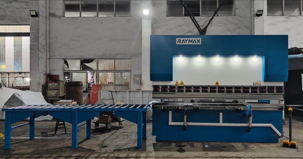
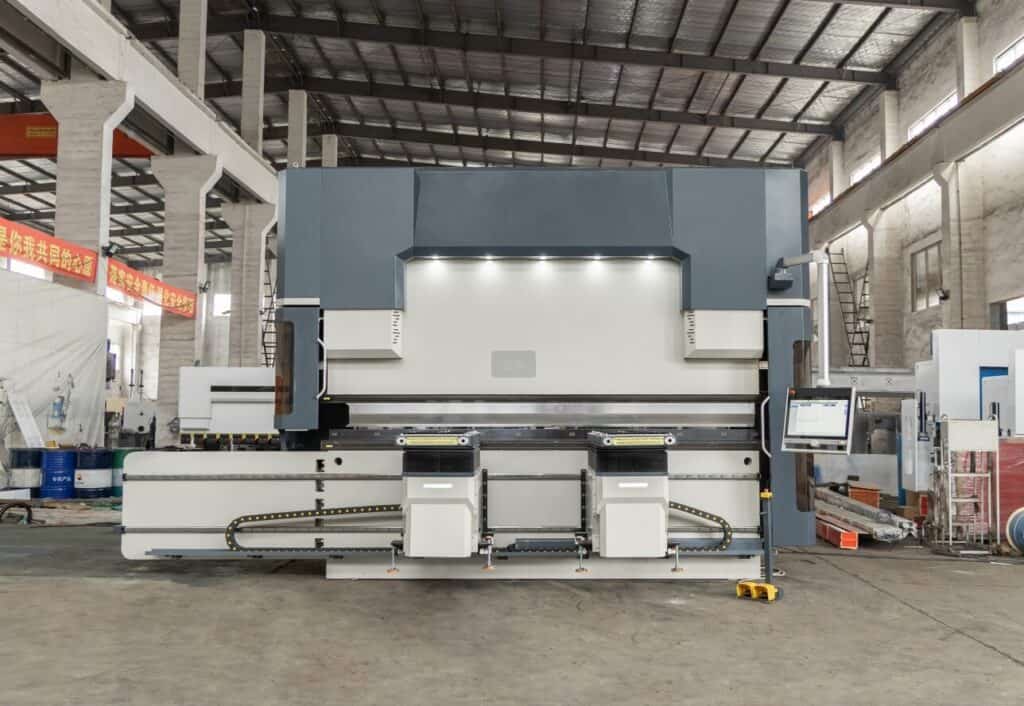
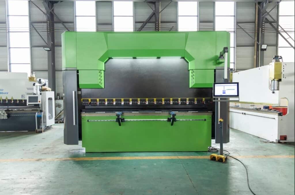
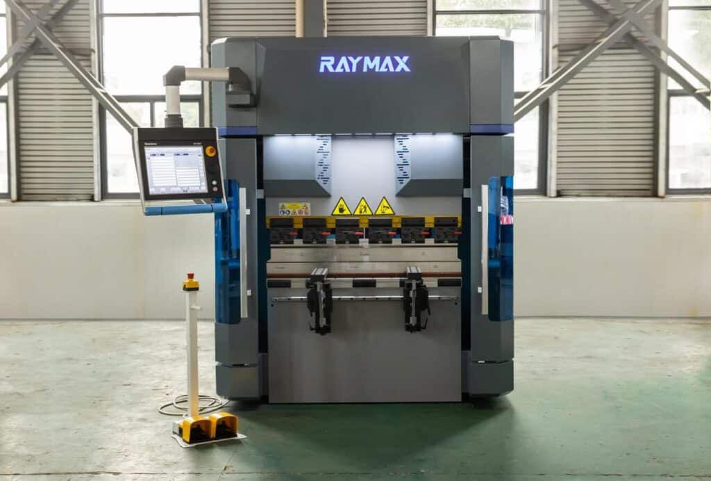
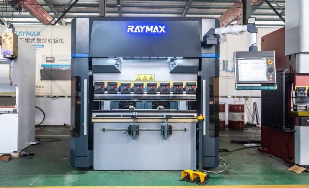
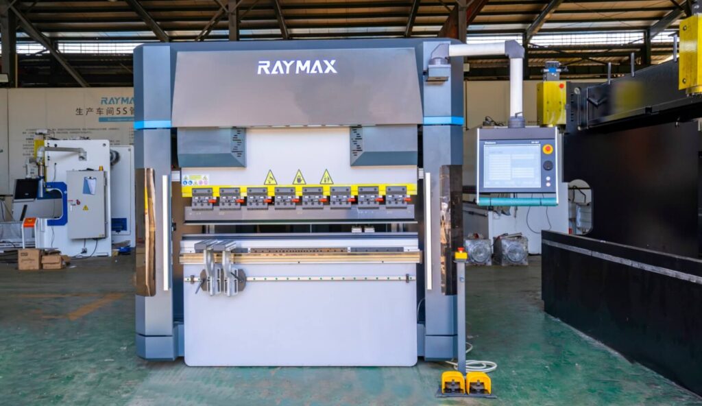
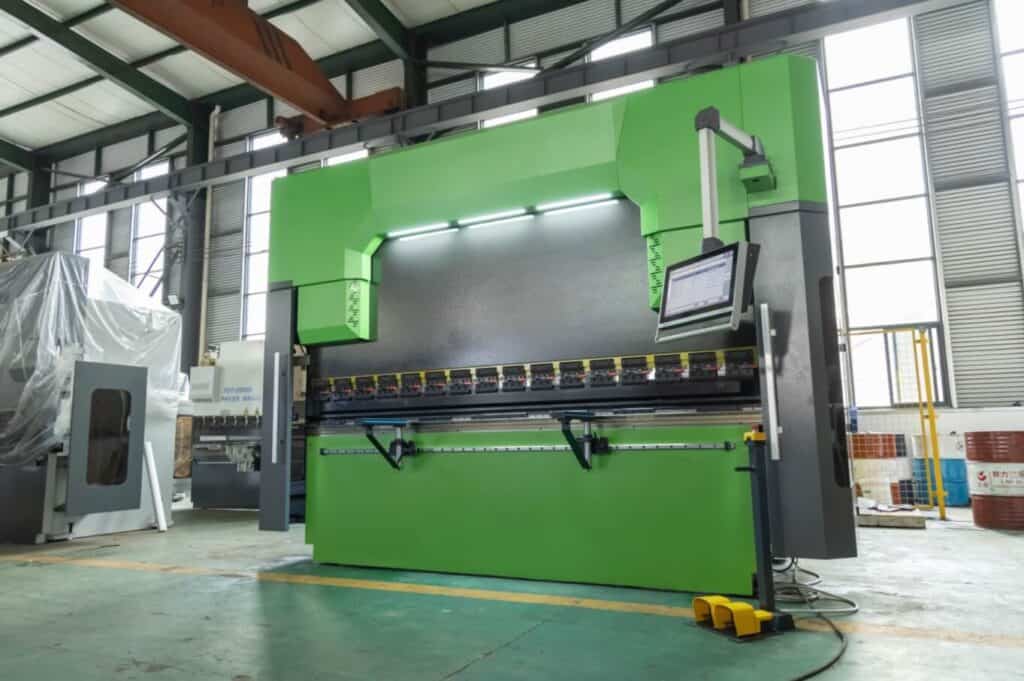
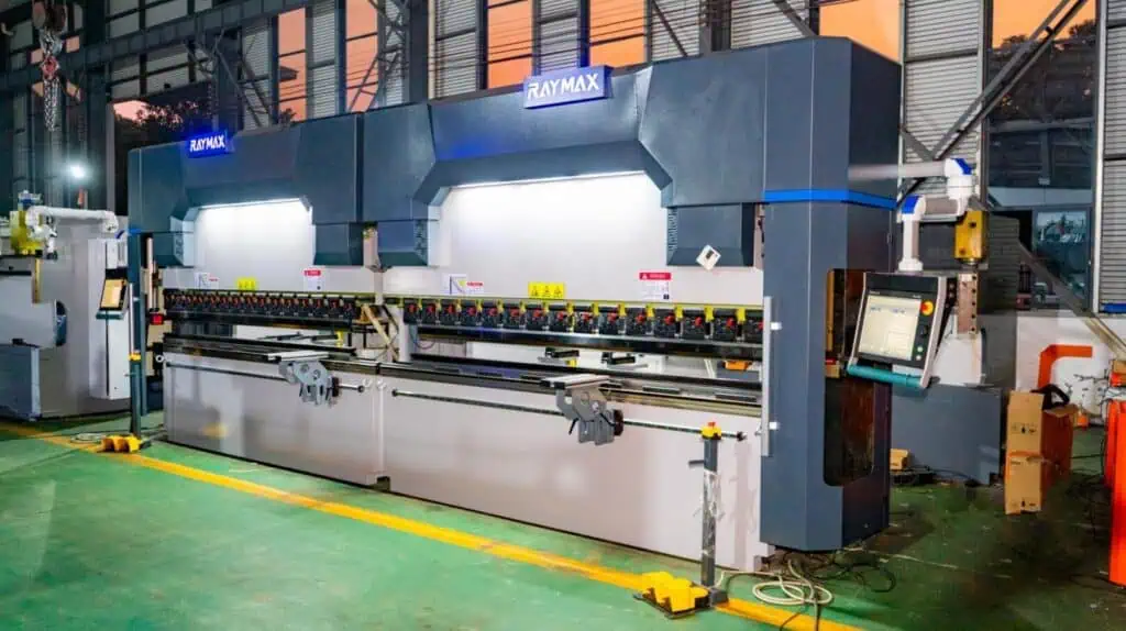
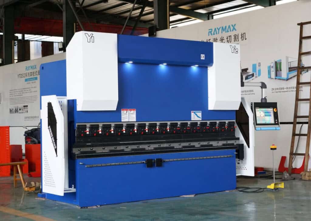
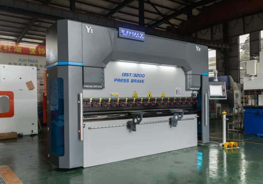
Press brake is an indispensable core equipment in the metal forming process,which is used for batch bending of metal sheets.The existence of press brake has greatly improved the quality of part forming,production cycle and industrial management efficiency in modern production operations.Each component ensures its efficient,precise and stable operation.
Today,I will explain in detail each key component and its function of the press brake to help you provide important help for subsequent equipment selection,component upgrade and maintenance.
Comprehensive analysis of press brake machine parts
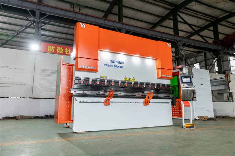
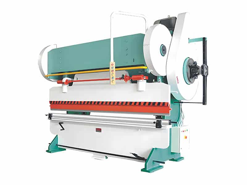
1. Mechanical system
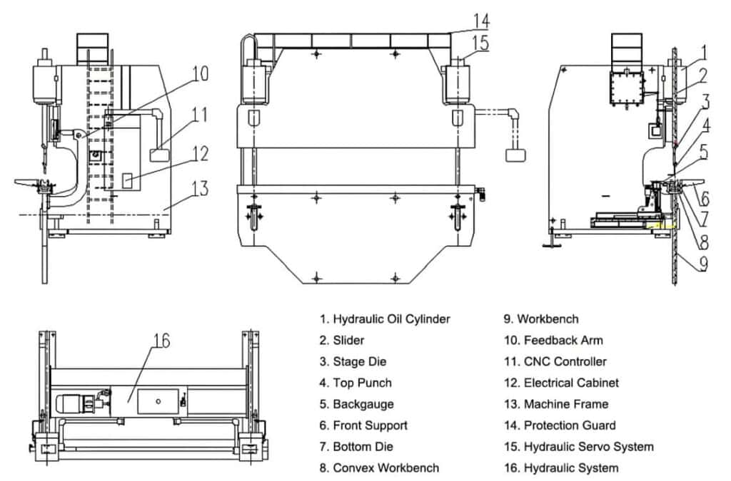
Composition structure:frame,top beam(upper beam),bed(lower beam),workbench,etc.;
Detailed explanation of the functions of each component:
a. Frame
The frame is forged and welded with high-strength steel,which is used to bear all the loads of the machine and fix and support other components.The frame ensures the stability of the bending operation process and assists in uniformly distributing stress.
b. Top beam(upper beam)
The top beam is the punch,which is equipped with an upper die.The sheet material is pressed into the bed(the bed is equipped with a lower die)by vertical downward pressure,thereby completing the entire action of sheet bending.Therefore,the accuracy of the punch movement is an important part of precise bending.Modern press brake machines are generally equipped with advanced control systems to accurately control the punch movement.
c. Bed(lower beam)
The bed is placed horizontally under the punch to support the sheet material and tools.The bed is generally forged with high-strength steel and usually has grooves or notches to match various molds.
Note:The top beam and bed are collectively called sliders.
d. Workbench
An auxiliary component,mainly used to place the raw sheet material during processing.
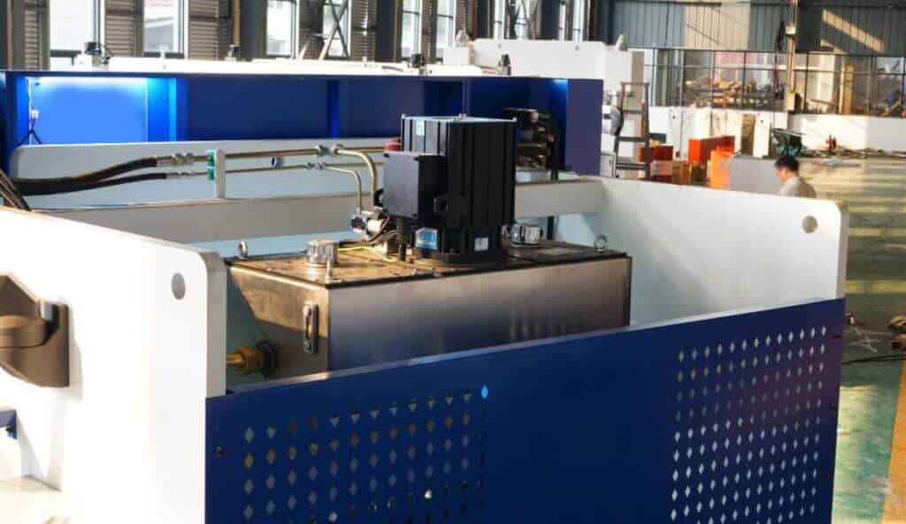
2. Hydraulic system
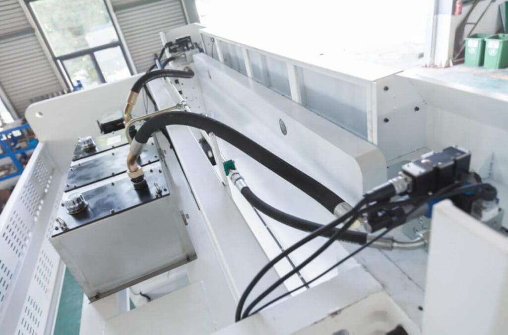
The hydraulic system is installed on the frame,with one cylinder on each side,which mainly controls the pressure and flow of the hydraulic cylinder.
Main components:engine,hydraulic pump,control valve,cylinder,hydraulic circuit,etc.
a. Motor
Refers to the engine(electric motor),which is the power source for the operation of the equipment. After the motor is started,it drives the hydraulic pump to provide a steady stream of power for the entire hydraulic system.
b. Hydraulic pump
That is,the power unit or motor is the heart of the equipment. The hydraulic pump converts the mechanical energy delivered by the motor into the pressure energy of the liquid and supplies it to the system. There are many types of hydraulic pumps,mainly including:
c. Hydraulic control valve
That is,the valve is used to control the direction,flow and pressure of the hydraulic oil in the system,so that the actuator maintains linear motion and completes the required work tasks. Types of valves include:
d. Cylinder
Used to store hydraulic oil,help remove moisture and air in the system,and compensate for changes in quality caused by actuator movement and temperature changes. Too high or too low hydraulic oil will cause the overall pressure of the system to change. Please check the oil level regularly and clean it in time.
Hydraulic cylinders are usually filled with hydraulic oil and are used to drive the vertical movement of the slider. They are mainly divided into single-acting cylinders and double-acting cylinders.
f. Hydraulic circuit
The network composed of pumps,valves,cylinders and pipes connected to each other determines the efficiency and performance of the system operation. It needs to be properly maintained regularly. Maintenance work includes ensuring that all connections are firm and preventing leakage.
g. Auxiliary equipment
Including pressure gauges,coolers(auxiliary heat dissipation),oil-water separators,oil mist collectors,filter elements,pipe fittings,pipe connectors,mufflers and other signal converters,etc. The existence of auxiliary equipment ensures the parameter stability of system operation.
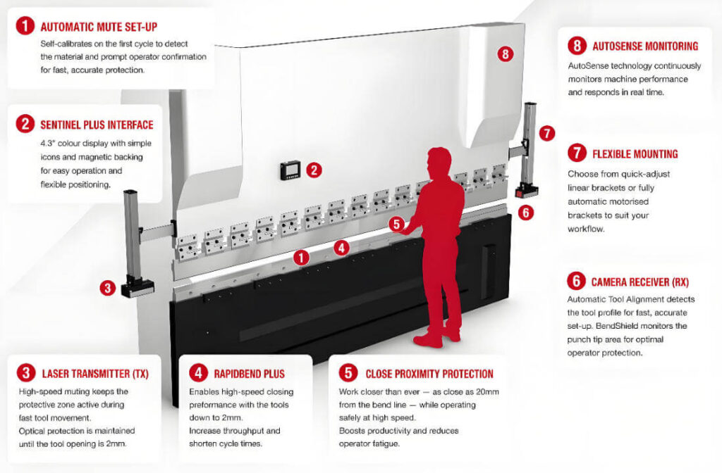
3. Control system
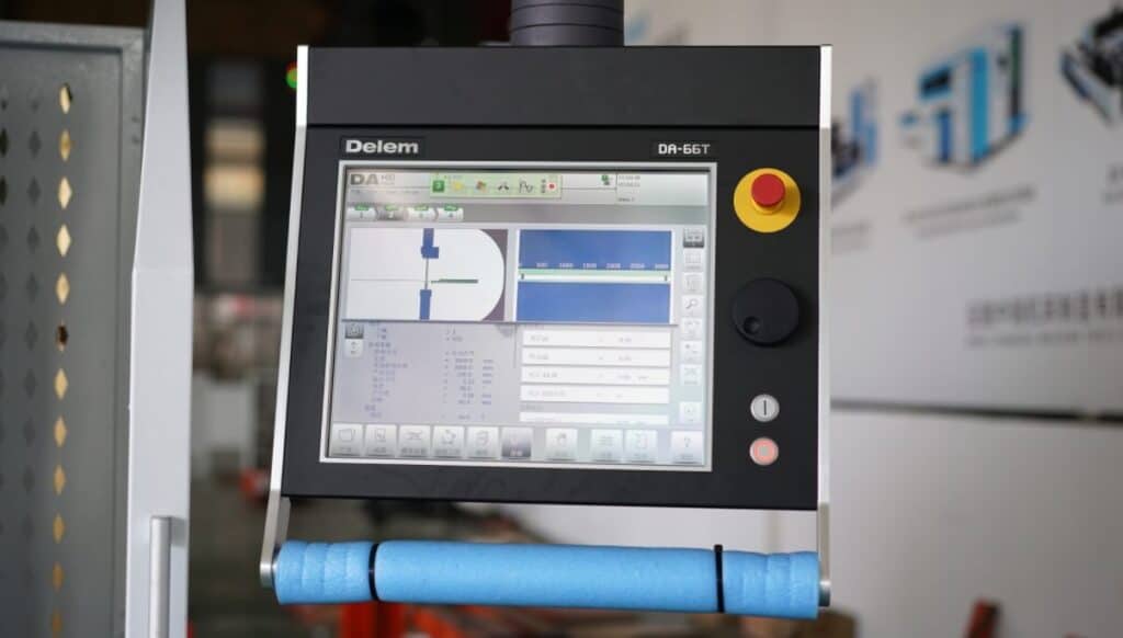
The control system is the brain of the press brake,which is generally divided into NC control system and CNC control system.
The control system provides a variety of efficient 2D or 3D graphic programming.The operator inputs instructions in the user interface to form a number of complex bending programs that meet the needs,and finally controls the axis movement of the press brake(up to 8 axes),and stores them for subsequent use at any time.Advanced control systems such as Delem DA-69T and CYBELEC CybTouch 15 PS are usually equipped with multiple automation functions such as automatic tool change,automatic compensation,angle and back gauge correction,etc.
The existence of the control system reduces manual intervention,and accurately controls the entire bending process through automatic programming,ensuring the high efficiency and accuracy of the bending operation.
Common control system introductions can be read: press brake control retrofit solutions
4. Electrical system
The electrical system is responsible for the power and automatic control of the machine.The main components include motors(modern press brake machines mostly use servo motors),sensors,and terminals.
a. Servo motors
Precisely control and adjust the operating position,speed and torque of the equipment.Compared with traditional motors,they have higher response speed and efficiency and more accurate control rate.
Sensors include position sensors,pressure sensors,and safety sensors,which monitor and ensure the accuracy and safety of the press brake through feedback devices.
b. Terminal blocks
The terminal blocks are installed in the distribution board,including circuit breakers,relays,contactors,etc.
5. Tool system
The tool system is used to define the bending angle and shape.The main components include punching,dies,tool clamping system,and tool alignment system.
a. Punch and die
Control and determine the bending angle and shape.Specific materials and thicknesses require targeted replacement of appropriate punches and dies.The main types include:
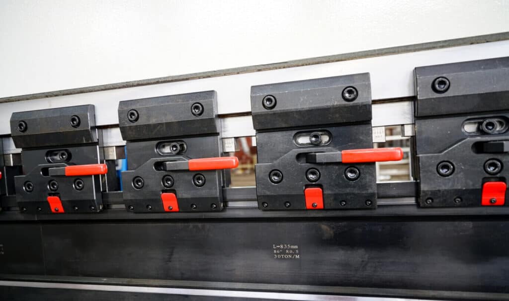
b. Tool clamping system
The tool clamping system is used to fix the die,including the upper clamp and the workbench clamp.The upper clamp fixes the upper die and automatically aligns to the lower die fixed by the workbench clamp.
c. Quick clamp
In addition to ordinary clamps,press brake manufacturers usually provide quick clamp upgrade services.As the name suggests,the quick clamp has the function of fast vertical tool change,which reduces the tool change time by 70%-80%.It is easy to install,durable,safe and efficient.The quick clamps on the market are available in three models:manual,pneumatic and hydraulic.
d. Tool alignment system
As the name suggests,it is used to center the mold to ensure bending accuracy.
The tool alignment system is divided into laser alignment and mechanical alignment.Mechanical alignment uses mechanical guides and blocks to center the mold,which is mostly used in manual or semi-automatic press brake machines.Modern automatic press brake machines mostly use laser alignment,which is efficient and accurate,greatly shortens the setting time,and speeds up the bending process.
6. Back gauge
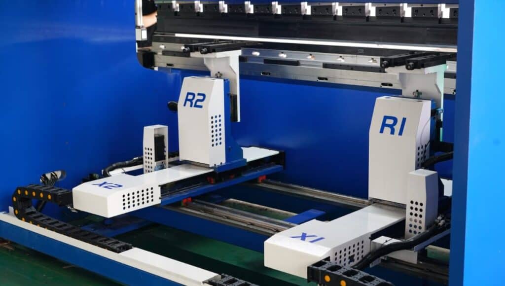
The press brake back gauge is located at the rear of the press brake.It is an adjustable block or finger,usually sold together with the press brake. Most backgauges are controlled by the CNC system of the press brake and can move on 6 different motion axes.Each motion axis is guided and controlled by an independent motor to accurately locate and adjust the position and length of the metal parts to be formed before bending to ensure accurate repeatability of the bending.Among them:
The backgauge moves to a specific position and length through the above 6 axes,which can accurately meet the bending requirements of different processed parts.
Backgauge subdivision components:
a. Backgauge sensor
Backgauge subdivision components:
b. Backgauge controller
When the backgauge sensor transmits a signal,the backgauge controller controls the backgauge rod to adjust and accurately position the workpiece.
c. Back gauge rail
The back gauge rail is used to support and guide the movement of the back gauge rod to ensure stability and accuracy during movement.
d. Back gauge rod
The back gauge rod is precisely controlled by the back gauge controller and supported by the back gauge rail.It is driven by electric or hydraulic drive to move and adjust the position of the stop finger.It is a rod-shaped component used in conjunction with the stop finger.
e. Stop finger
Press brakes usually have multiple stop fingers,which are configured according to the actual processing requirements.They are point contact.The longer the length of the bent sheet metal is,the more stop fingers are configured.When the back gauge is displaced,the stop finger moves smoothly(can also be adjusted up and down)to the specified position through the linear guide rail to mark the size of the workpiece.
7. crowning system
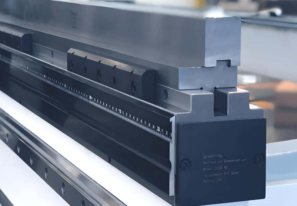
Function: used to compensate for the deflection of the slider under load,ensure that pressure is evenly applied throughout the bending process,and reduce material deformation.
The crowning system is used to compensate for the deflection of the bed and slide of a long-stroke press brake(≥8 feet/2.4 meters)under load,avoiding material deformation caused by uneven force on the workpiece during the entire bending process.
The crowning system has a variety of compensation functions,including:angle compensation,length compensation,gap error compensation,etc.
The compensation technology includes shim compensation method,servo electronic pulley system,hydraulic addition system and mechanical crowning system compensation method.Among them,the last compensation modification scheme is subjectively popular in modern press brake machines.
8. 4V concentric die
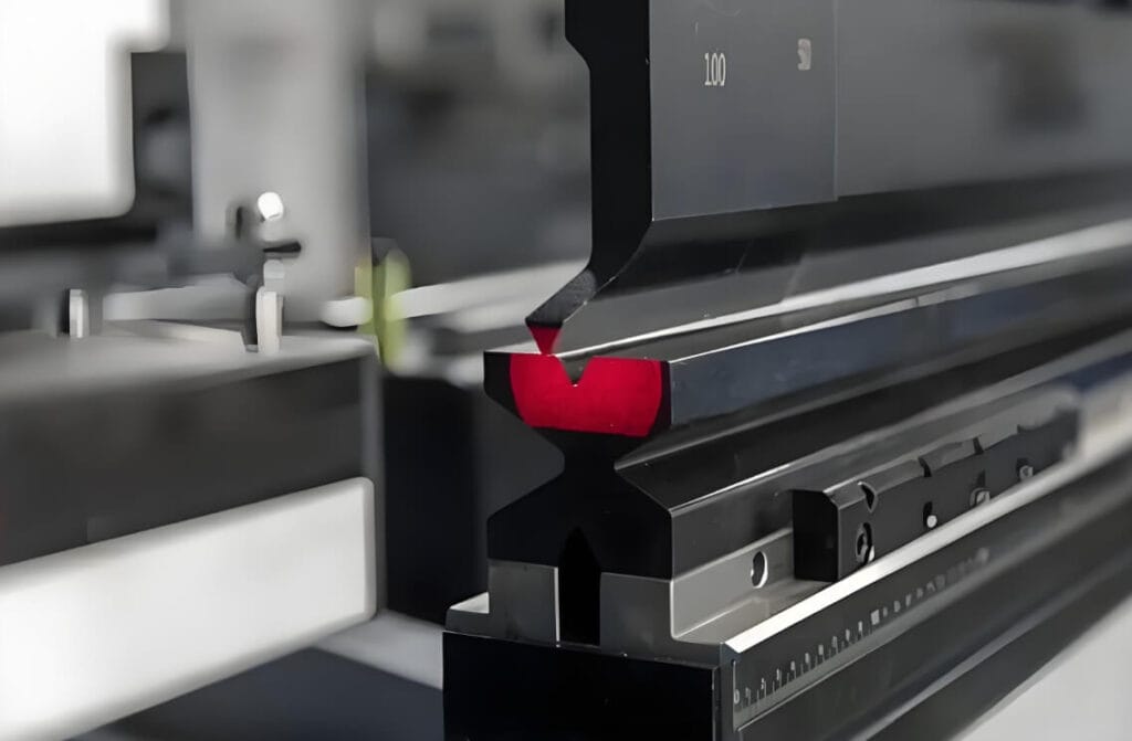
The 4V concentric die is used to manufacture high-precision bent parts and complements the back gauge.When processing parts,the back gauge places the required bending line in the center of the”V”-shaped opening of the die,so as to ensure that the die is always in the exact center during operation,thereby ensuring the accuracy of the bending.
9. sheet follower
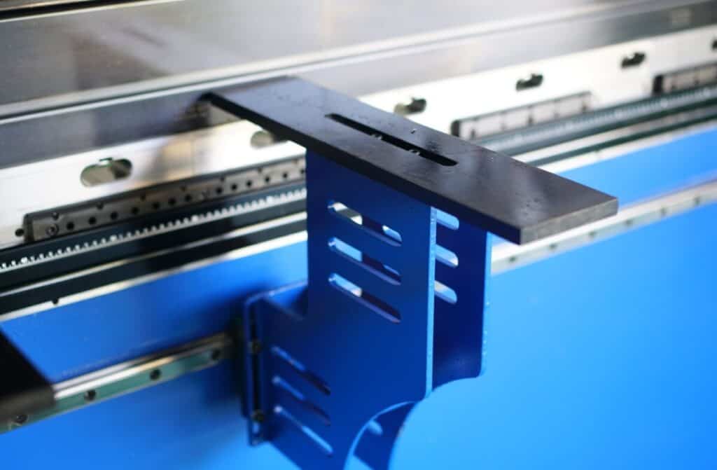
The press brake sheet follower (front support) is equipped with a guide rail that can be adjusted up and down and moved automatically.It is used to provide additional support for longer metal processing sheets during the bending process to prevent them from bending or deformation.
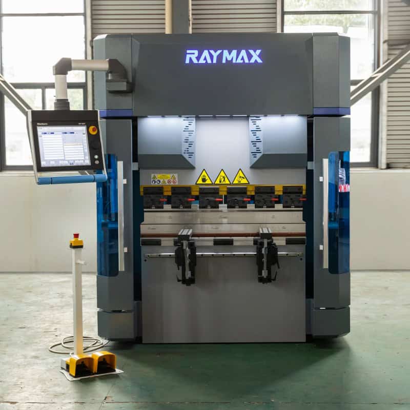
10. Foot Switch
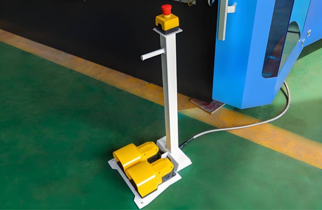
Foot Switch has emergency stop,cycle,and single-step remote control functions,which are used to ensure that the operator can operate the equipment in a safe manner.It is one of the four main components of the press brake(operator,equipment,system,Foot Switch).
Brand foot switches(such as PIZZATO)are mostly equipped with high-level protection configurations,which are ergonomic,ensuring operational comfort while effectively preventing the intrusion of dust and liquids,and adapting to various harsh working environments.
11. Grating Ruler
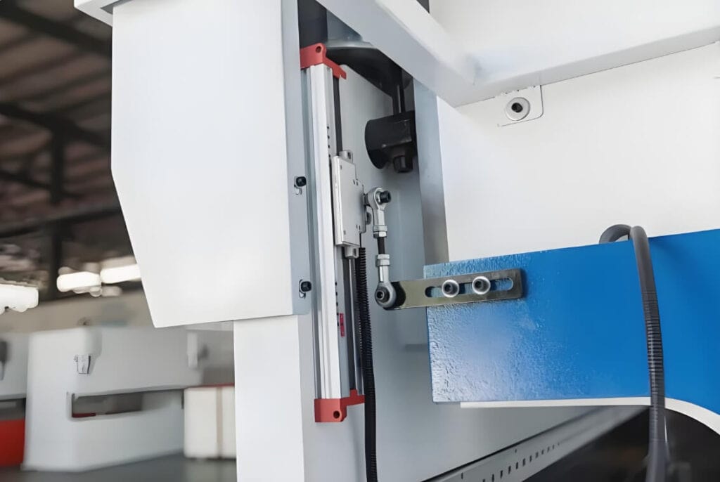
The grating scale sensor is installed on the linear guide rail,which can move smoothly and adjust up and down to adapt to workpieces of different sizes and shapes.It is used to accurately measure the position of the slider(upper and lower molds)in real time to improve the bending accuracy.
Maintenance tips for press brake machine components
In order to ensure the reliable operation of each component and avoid the occurrence of failures,it is recommended that the purchaser regularly perform maintenance and inspection work on it.Common maintenance steps are referenced:
Press brake parts purchase guide
1. Find the press brake supplier to upgrade directly
If you already have one or more press brake machines and want to upgrade your related parts,it is recommended to contact your equipment supplier directly.They usually have targeted supporting equipment for the upgrade function of their own brand press brake machines,which can better match the various parameters of the machine,and there will be corresponding preferential policies for the purchased merchants.
2. Find well-known press brake parts brands
For example,brands such as Rolleri,Wilson,and Wila in the tooling clamping system,and brands such as DELEM,ESA,and CYBELEC in the control system.They are all mainstream professional press brake parts brands on the market,with rich and diverse types of parts and functions.While providing professional technical guidance,after-sales service is also guaranteed.The disadvantage is that it is usually more expensive to buy accessories from well-known brands separately.
Conclusion
The various components of the press brake complement each other and work together to ensure the precise and stable operation of the machine.Correct maintenance and inspection work is crucial to improving long-term production efficiency and product quality.Here is a final reminder to everyone to conduct comprehensive inspections of the equipment regularly to ensure the best operating status.For more press brake fundamentals and equipment issues,please pay attention to the latest reports from RAYMAX!
If there are any related technical issues that are not solved in the above article,please feel free to contact us at any time.Our technical team will answer your questions for free 24 hours a day,7 days a week to help you quickly enter the perfect bending production state!
Ready To Upgrade Your Metal Fabrication Line?
Email Us For A Free Consultation.
Related Blog
One-Stop Guide to Hydraulic Press Brake: Working Principle, Bending Process & Applications
Press Brake FAT/SAT Acceptance Checklist: Accuracy Tests, Tolerance & Documentation
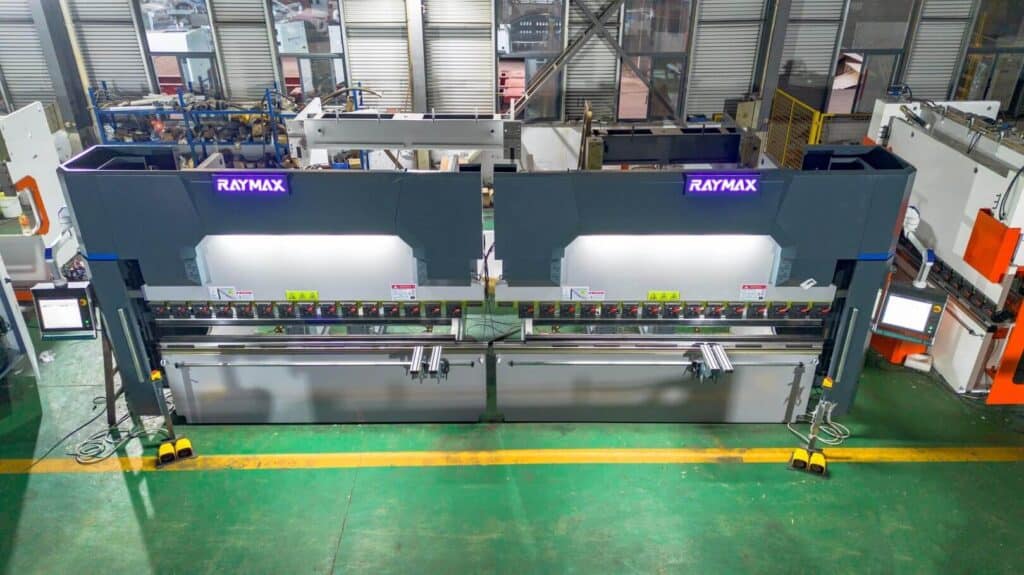
What Is a Tandem Press Brake? Benefits, Applications & Buying Tips
Press Brake Overview and Smart Selection Tips
Tooling & Clamping for High-Mix Production: Quick Clamp vs Hydraulic Clamp vs Manual Clamp ROI
What Is a Press Brake Used For? 16 Industry Applications and 8 Types of Bends
Definition, working principle and selection guide of hybrid press brake
Pneumatic Press Brake: Complete Guide, Advantages, Applications & Buying Tips
Press Brake Guarding Systems & Requirements: OSHA & ANSI Safety Guide
An Overview of Electric Press Brake Machines and Purchasing Tips
Top 10 Press Brake Manufacturers: How to Choose the Right Supplier
What Is a Sheet Metal Press Brake Machine? Working Principles, Bending Techniques & Buying Guide
Post Your Review
Share Your Thoughts And Feelings With Others