
Francis Pan
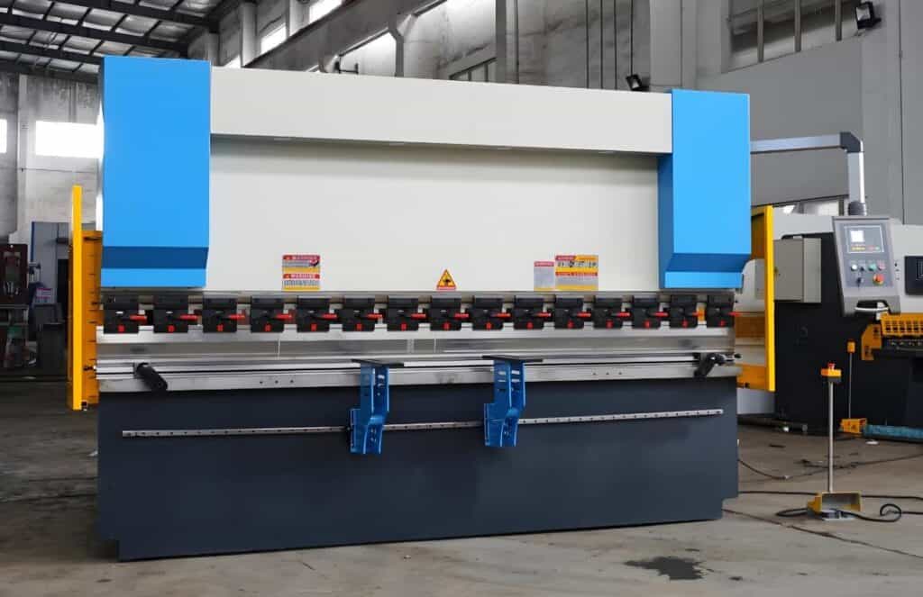
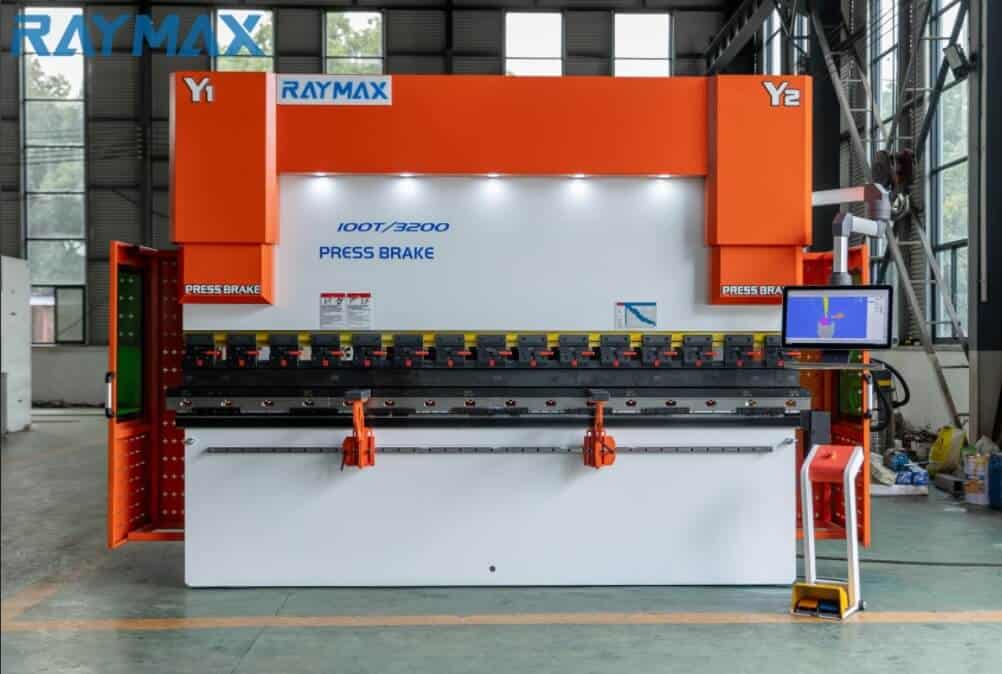
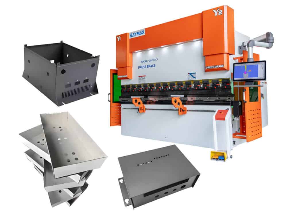
Francis Pan is the Foreign Trade Manager of RAYMAX, with over 10 years of experience in sheet metal fabrication equipment and CNC machinery. He has worked closely with manufacturers worldwide on press brakes, fiber laser cutting machines, fiber laser welding machines, and practical production-oriented metal processing solutions.
Top Guidelines
-1024x768.jpg)
-1024x768.jpg)
-1024x768.jpg)
-1024x768.jpg)
.jpg)
Table Of Contents
Stay in the the loop
Subscribe To Our Newsletter
Quick Answer
Quick Conclusion
The most commonly used process: By determining parameters such as bending angle (A), plate thickness (T), inside radius (R), K factor (K), etc., first calculate BA, then calculate OSSB or BD, and finally obtain the flat pattern length.
For consistent results: don’t rely on a single memorized K-factor. It is recommended to calibrate with test pieces and establish your own bending table or material database.
Reduce rework and scrap: To ensure stability, choose the right tooling, ensure machine accuracy/compensation is in place, and store test-bend results in a bend table (material database).
30 second comparison table
|
Name |
What it represents |
Most commonly used scenarios |
|---|---|---|
|
BA(Bend Allowance) |
The arc length along the neutral axis within the bending arc area |
CAD unfolding rules |
|
BD(Bend Deduction) |
The length deducted from the sum of the external lengths of the two flanges |
Workshop on-site calculation, quotation, process card |
|
K factor |
The proportion of the position of the neutral axis in the plate thickness |
Build a bend table and material database |
Why is “flat pattern length” the easiest to step on?
In the field of sheet metal bending, once the flat pattern length is calculated incorrectly, it may result in the final bent dimensions won’t match the design, causing rework or scrap. For some parts with holes, symmetrical parts, and assembly parts, it is even more troublesome.
In reality, many engineers may have the same confusion: they understand the formulas, but results are still inconsistent on the shop floor. In fact, the reason usually lies not in the formula itself, but in the K factor, inside radius, bending method, and consistency between the tooling and equipment.
This article will explain the concepts and relationships of BA(Bend Allowance), BD (Bend Deduction), and K factor, provide calculation examples, and teach you how to reduce trial and error and rework rates through CNC numerical control systems, specimen calibration, and bending tables.
Core premise: What is the neutral axis?
What happens to the material during bending?
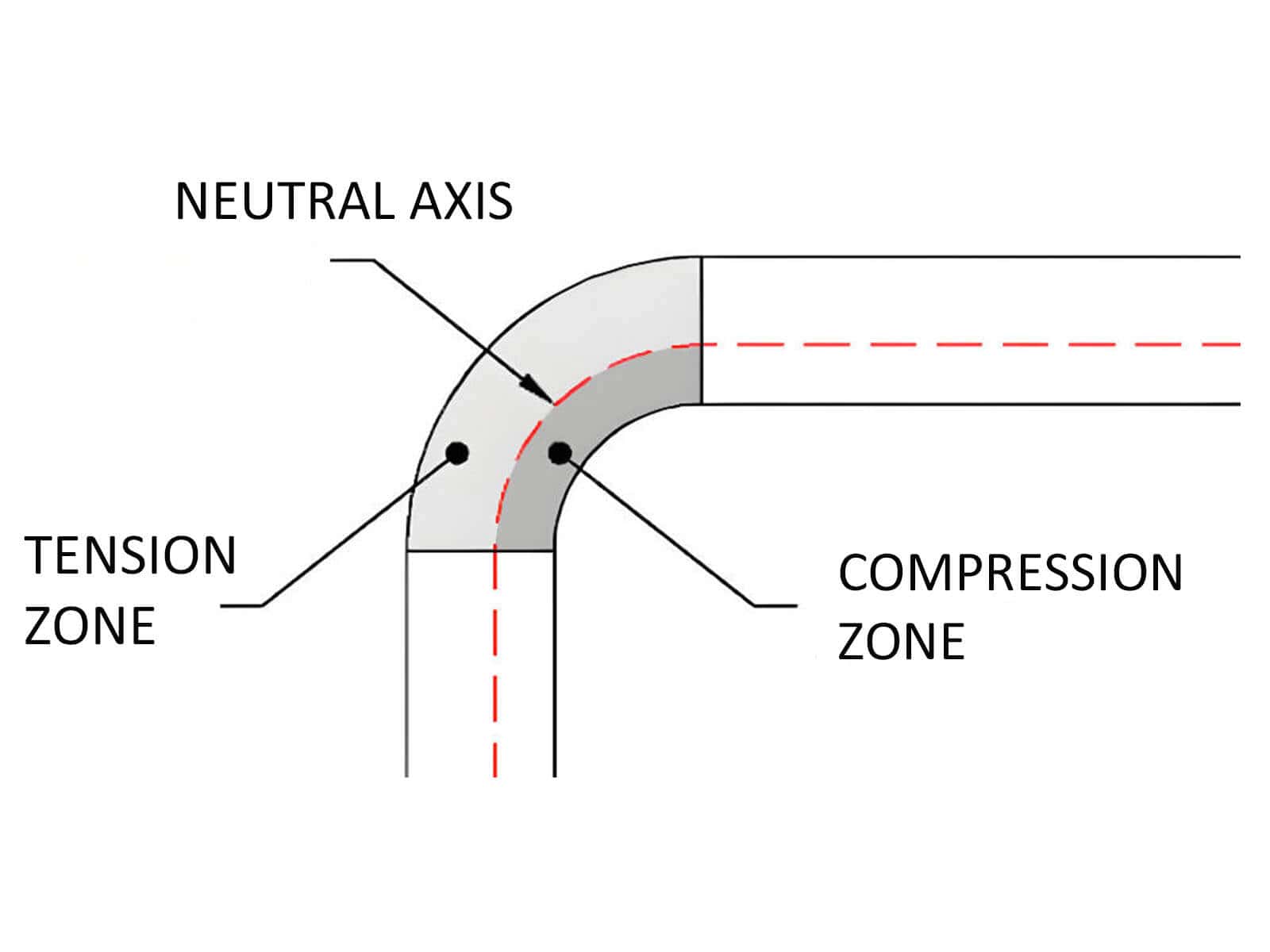
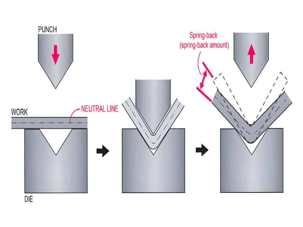
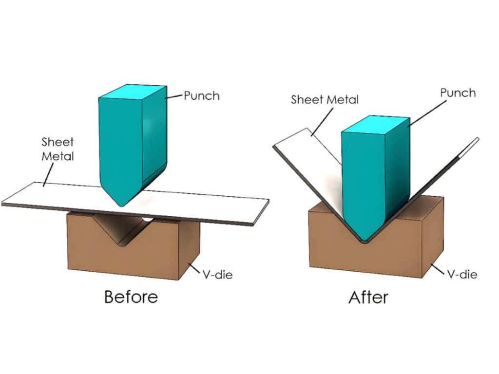
When the sheet metal is pressed into the lower die, the material on the outer side of the sheet metal will be stretched, while the material on the inner side will be compressed. The ratio of stretching and compression will vary with the thickness of the material, the radius of the inner corner, and the bending process.
Definition and significance of neutral axis
Between the stretching zone and the compression zone, there is an imaginary line/plane that does not produce significant stretching or compression, has the smallest deformation, and has the most stable length. This is called the neutral axis.
The essence of our calculations is to establish a mathematical model around the neutral axis and determine the required material length for the bending area.
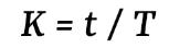
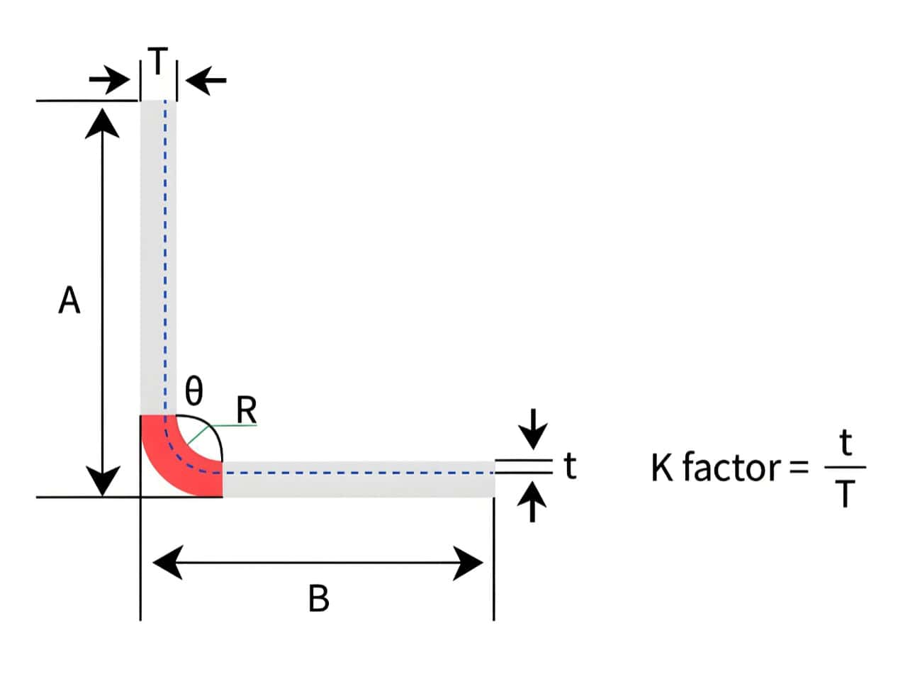
What is K-Factor
K-Factor Definition Formula
Why is the K factor important?
Because the K factor determines the position of the neutral axis, which in turn affects the arc length of the neutral axis, i.e. BA, ultimately affecting the flat pattern length and the size of the bent workpiece. Once the K factor is selected incorrectly, it is likely to lead to incorrect calculation of the flat pattern length, resulting in rework or scrap.
Why is K not a constant
K cannot be used as a fixed empirical value because its value is influenced by the following factors:
Starting Range of Experience
When starting the calculation, we usually use a common range of K values as the starting point, typically between about 0.30-0.50.
But this is only a starting point for preliminary estimation, and the final K value should be based on the calibration of the test piece.
BA vs BD: Definition, Formulas, and Core Differences
BA (Bend Allowance)
Definition: Refers to the arc length along the neutral axis within the bending arc area, which is the actual length of material consumed during the bending process.
BA calculation formula:
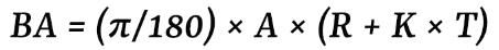
A=bending angle, R=inside radius, T=sheet thickness, K=K factor.
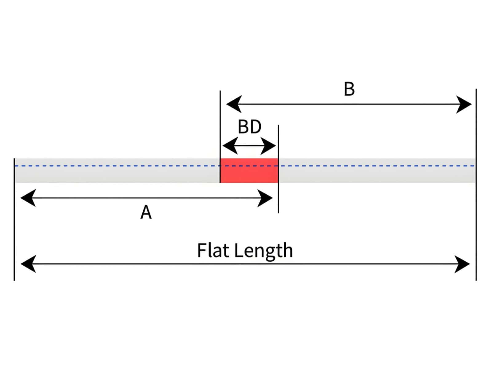
BD(Bend Deduction)
Definition: Due to the stretching and compression of the material during bending, in order to ensure the correct external dimensions after bending, we usually add the lengths of the two external flanges of the bent part and subtract another number to obtain the correct flat pattern length. The deducted amount is BD.
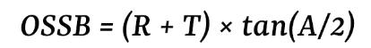
Before calculating BD, we need to first understand the concept of OSSB (Outside Setback) , which is the setback distance (related to R, T, and angle) from the theoretical outside corner to the tangent point, used as an intermediate value to calculate BD.
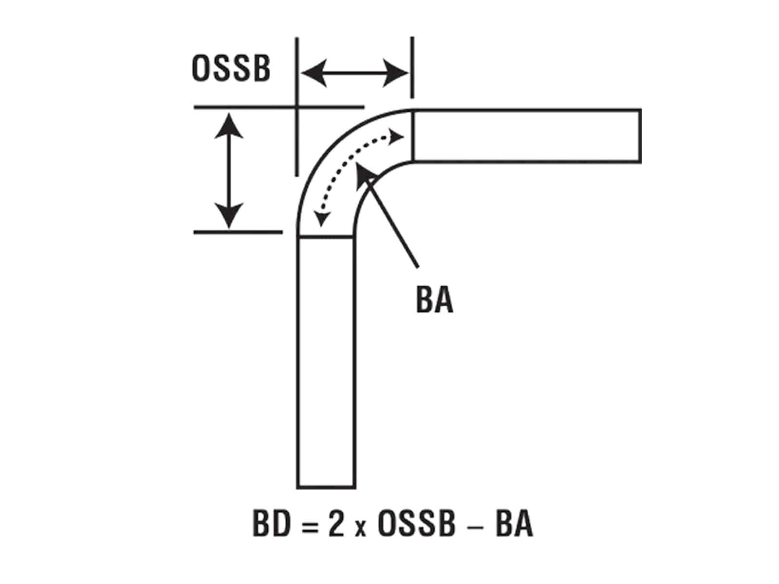
OSSB calculation formula:
BD calculation formula:
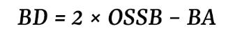
Table Conclusion
|
Project |
BA |
BD |
|---|---|---|
|
What is the most common input in your hand |
A (bending angle), R (inside radius), T (plate thickness), K (K factor) |
Two flange external dimensions and A, R, T, K |
|
Is it “adding” or “subtracting” in calculations |
Usually added to the arc length of each bend |
Usually subtracted from the external dimensions of the two flanges |
|
Applicable scenarios |
Basic calculation rules of CAD software |
Quick calculation, quotation, process card, and establishment of bending table on site in the workshop |
|
Common Misconceptions |
Treating K as a constant and mistaking the inside radius (R) on the drawing for the actual formed inside radius (R) |
Incorrect use of OSSB formula |
How to do a single 90 °bend
Gradually expand the size calculation process
Step 1: Confirm the material thickness T, bending angle A, and target/actual inside radius (R)
Step 2: First, select a starting K value within a common range, and then calibrate it through trial bending
Step 3: Calculate BA value
Step 4: Calculate OSSB and BD values
Step 5: Calculate the flat pattern length

Five common pitfalls for multi pass bending/perforated parts
Calculation Example
Example 1:
Here is a complete calculation procedure:
Condition: Low carbon steel, T=2mm, A=90 °, R=2mm, L1=50mm, L2=50mm, K=0.44 (initial value)
① Calculate BA
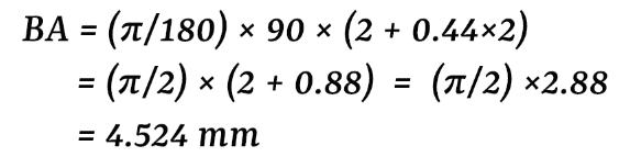
② Calculate OSSB
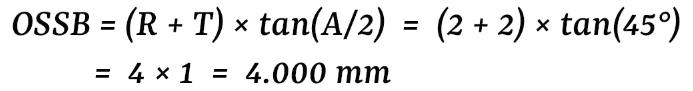
③ Calculate BD
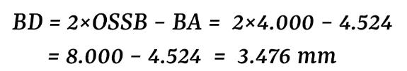
④ Calculate the flat length

Example 2:
If only one variable is changed, what will happen to the flat length?
Only change K: 0.44 → 0.33
① Calculate BA
.jpg)
② Calculate OSSB
.jpg)
③ Calculate BD
.jpg)
④ Calculate the flat length
.jpg)
.jpg)
We can see that after changing the K value from 0.44 to 0.33, there is a difference of 0.346mm in the final flat pattern length.
Only change R:2mm → 3mm
① Calculate BA
.jpg)
② Calculate OSSB
.jpg)
③ Calculate BD
.jpg)
④ Calculate the flat length
.jpg)
.jpg)
We can see that after changing the R value from 2mm to 3mm, there is a difference of 0.429mm in the final flat length.
So, paper calculations must be deeply bound to the consistency of actual R, tools, bending methods, and equipment. A small systematic error will lead to a deviation in the final flat length, resulting in rework or scrap.
Why is your unfolding always inaccurate?
Inconsistencies between actual fillet R and drawing R
In the most common air bending process, the actual formed inside radius (R) is generally determined by the lower die V-die opening, the material, and the process. The R here is different from the R in the drawing. If you fill in the R value in the calculation formula as shown in the drawing, but the actual R after bending may be larger or smaller, it will cause calculation errors in BA, OSSB, and BD, resulting in deviations in the flat length.
Different bending methods result in different springback and neutral axis positions
Equipment and Process Consistency
Even if the formula is correct, the final accuracy cannot be achieved without the stability of the equipment and process. Mainly reflected in:
How do tools and equipment affect the calculation results?
How V-die opening affects the actual inside radius (R)
The V-die opening size directly determines the actual size of the inside radius (R), thereby affecting the BA, BD, and K values. If the selection of V-die opening is incorrect, it may lead to deviation in the calculation results.
So, it is recommended to bind and manage the unfolding rules with “material, thickness, V-die opening size, bending method”.
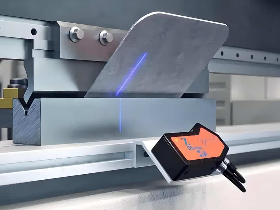
Machine tool accuracy and consistency
How to reduce trial and error and rework of Raymax CNC press brake
In short, the accuracy of flat length is not only achieved by calculation, but also by the system capability of “correct calculation+specimen calibration+stable execution”.
Free tool download
Resource 1: Sheet Metal Unfolding Automatic Calculation Table
Function: Simply input parameters such as T, R, A, K, and the table will automatically output BA, OSSB, BD, and flat length.
Resource 2: Bend Test Sheet Calibration Record
Function: Record material, thickness, V-die opening size, bending method, target angle, measured angle, and reverse calculate actual K/BD value.
Value: Help factories establish their own bending tables and reduce trial bending.
Resource 3: Inquiry/Process Parameter Checklist
Including: material, thickness, bending length, angle, tolerance, target inside radius (R), V-die opening size, batch size, surface requirements, etc.
Value: The more complete the parameters, the faster and more accurate the engineering evaluation and quotation will be.
The above tables can help you quickly complete basic calculations; If you wish to convert the calibration results of the test piece into a bending table and improve batch consistency, please feel free to submit your relevant parameters to us. We can provide you with suitable bending schemes and equipment configuration suggestions.
Download method:
Click here to download
CAD/CAM software setting guide for avoiding pitfalls
BA/BD/K are interchangeable in software, but the rules must be consistent with the workshop
Many CAD/CAM software allow you to define bending rules using K, BA, or BD, which can often be converted to each other in the software. But the key is that the rules used by the design department in the software should be consistent with the actual bending results in the workshop.
It is strongly recommended to establish a unified bending table in the background to ensure that the rules used in the software and the actual bending in the workshop use the same program, avoiding the situation of “designing one set, workshop one set”. To build this workflow more systematically, you can also read our press brake software basics and selection guide, which explains how CNC software, CAD/CAM integration, material databases, and production feedback help reduce bending errors.
Common Error List
Conclusion
The core process of unfolding calculation is to determine the neutral axis position, determine the K factor, calculate BA/BD, and obtain the final flat length.
However, the formula is only a starting point. To maintain high consistency and stability in mass production, it is necessary to rely on correct calculations, strict specimen calibration, and the stability of equipment and processes. Unifying CAD rules with workshop rules is the most effective way to significantly reduce our rework and delivery risks.
Please submit your materials, thickness, bending length, angle, target inside radius (R) and V-die opening. Raymax engineers will assist you in creating a bending table and provide you with CNC press brake solution and equipment configuration suggestions.
If you need to evaluate the tonnage, length, number of axles, and tooling scheme that are suitable for your working conditions, you can also provide us with your parameters, and we will provide professional technical consultation and quotation suggestions.
Ready To Upgrade Your Metal Fabrication Line?
Email Us For A Free Consultation.
Frequently Asked Questions (FAQs)
Related Blog
Press Brake Crowning Troubleshooting: Fix Uneven Bend Angles Across Long Parts
How to Improve Press Brake Bending Consistency: Causes, Checks & Solutions
How to Measure Press Brake Bending Angle: Tools, Methods & Calibration Pitfalls
.jpg)
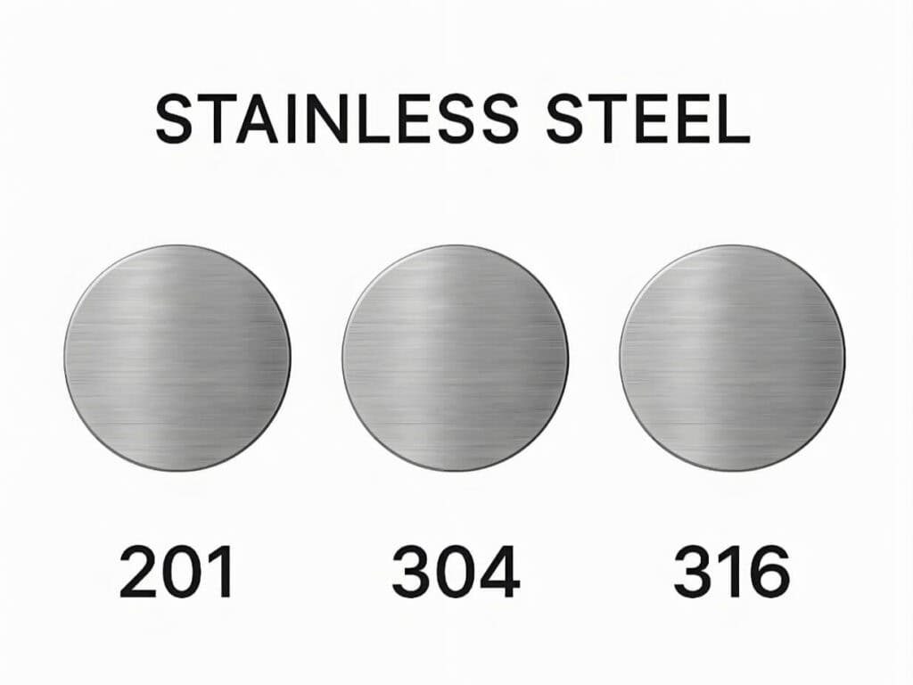
Stainless Steel Bending Force: 304 vs 316 (Correction Factors, Springback & V-Die Selection)
-1024x768.jpg)
Press Brake Tonnage Comparison: Air Bending vs Bottoming vs Coining (How Force Changes + Safety Margin)
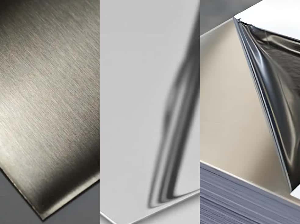
Non-Marking Press Brake Bending: How to Prevent Scratches on Brushed, Mirror-Finish & Film-Protected Sheets
Electrical Enclosure Bending: Flat Pattern, Flange Accuracy & Fit-Up Issues
Press Brake Bending Accuracy Checklist: 10 Quantified Factors to Inspect
Press Brake for Stainless Steel: Tonnage, V-Die Selection, Springback & Surface Protection
How to Reduce Springback in Press Brake Bending (SS/AL/MS Checklist)
V-Die Opening Rule (6t/8t/10t): How to Choose Die V for Accurate Bending
Press Brake Crowning Explained: Deflection, Angle Variation, Adjustment & System Comparison
Post Your Review
Share Your Thoughts And Feelings With Others