
Francis Pan
Francis Pan is the Foreign Trade Manager of RAYMAX, with over 10 years of experience in sheet metal fabrication equipment and CNC machinery. He has worked closely with manufacturers worldwide on press brakes, fiber laser cutting machines, fiber laser welding machines, and practical production-oriented metal processing solutions.
Top Guidelines
-1-1024x768.jpg)
-1024x768.jpg)
-1024x768.jpg)
-1024x768.jpg)
Table Of Contents
Stay in the the loop
Subscribe To Our Newsletter
Quick answers
Note: The discussion in this article regarding V-die openings, required bending force, and springback compensation primarily applies to air bending processes. If bottoming or coining is used, the required tonnage, die matching, and springback characteristics will differ significantly.
30-Second Lookup Table
|
Material |
Tonnage Factor vs. Mild Steel |
V-Die ratio start |
Springback tendency |
Surface risk |
|---|---|---|---|---|
|
304 |
≈1.5 times |
≥8T |
High |
Medium |
|
316 |
≈1.5-1.6 times |
≥8T |
High |
Medium |
|
201 |
≈1.4-1.5 times |
≥8T |
Relatively high |
Medium |
|
Mirror-finish stainless steel |
≈1.5 times |
≥10T-12T |
High |
Extremely high |
|
Brushed stainless steel |
≈1.5 times |
≥10T |
High |
High |
|
Film-coated stainless steel |
≈1.5 times |
≥10T |
High |
High |
If we primarily manufacture stainless steel parts, then in addition to considering the machine’s tonnage, the tooling setup, crowning, back gauge accuracy, and surface protection are equally important.
Why is stainless steel more “demanding” to bend than ordinary steel?
Key challenges
The difficulty of bending stainless steel stems primarily from its physical properties.
On-site issues: Why does 2mm stainless steel fail?
Common causes may include the following:
The Real Challenge of Stainless Steel Bending: Not Whether It Can Be Bent, but Whether It Can Be Bent Consistently
When it comes to bending stainless steel, the real challenge isn’t whether the first piece can be bent, but whether it’s possible to consistently produce parts with the correct angles and dimensions during mass production while maintaining a high level of surface quality.
Which industries rely most heavily on stainless steel bending?
Industries that demand high precision and excellent surface quality, such as elevator decorative panels, high-end kitchenware and food processing equipment, medical device housings, architectural trim, and high-end enclosures and cabinets.
5 key input parameters before bending
Material grades
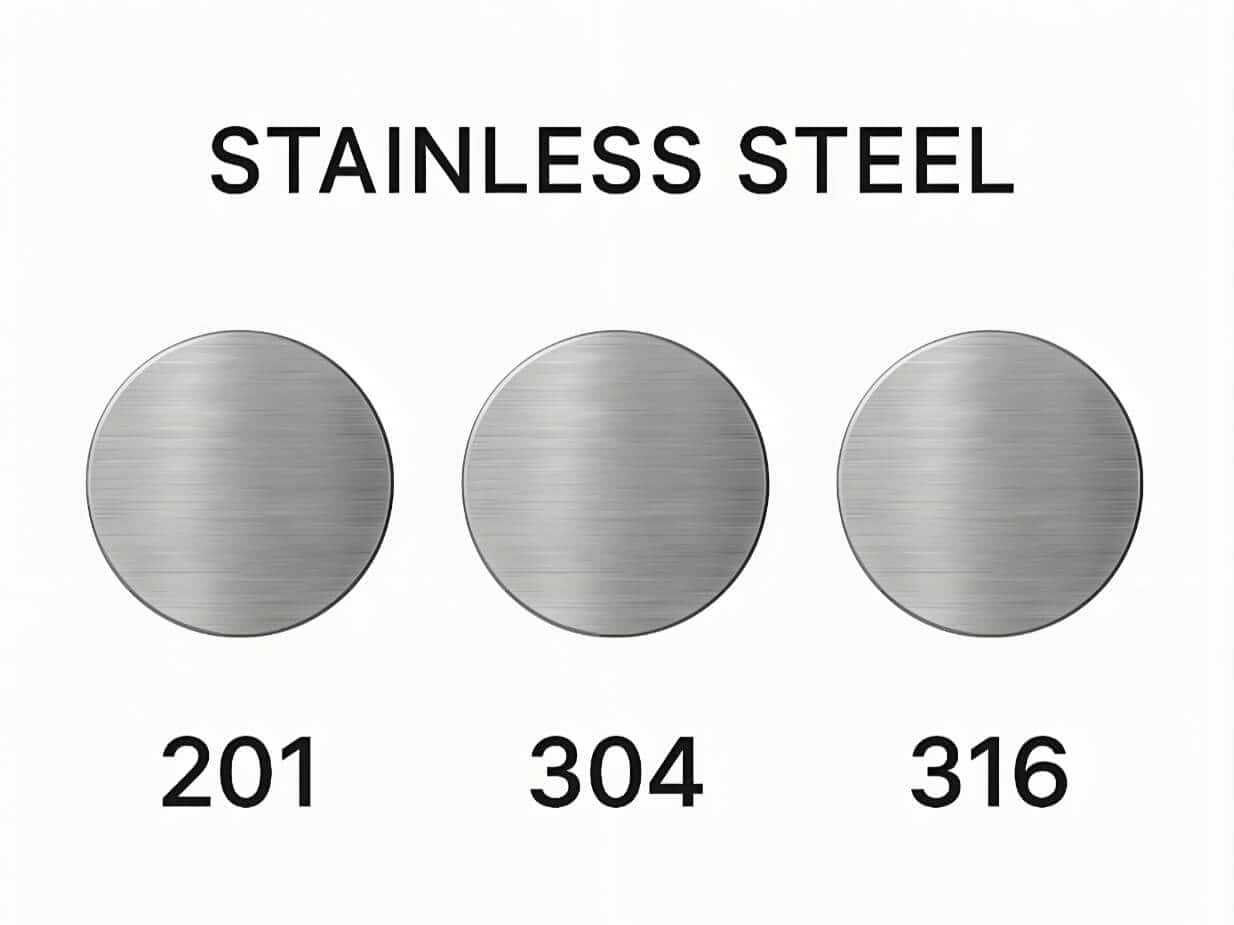
The different material grades—such as 304, 316, and 201—should not be treated as interchangeable.
Although they are all stainless steels, their strength and work-hardening characteristics vary. For example, 304 is the most widely used grade, while 316 typically provides superior corrosion resistance; meanwhile, the mechanical properties and formability of 201 stainless steel may vary depending on the supplier, batch, and condition.
Therefore, for applications with stringent requirements, we must establish parameters based on the material certificate and test results for the specific batch.
Sheet thickness
Changes in sheet thickness result in changes to a range of parameters. Thin, medium, and thick sheets each have different requirements regarding the required tonnage for bending, V-die width, inside radius, and minimum bend length.
Bending length
When bending workpieces of different lengths, factors such as the total tonnage, load per unit length, table deflection, angle consistency, and support requirements are all affected. The longer the workpiece, the greater the potential difference in angles between the center and the ends during the bending process. In such cases, the machine must be equipped with a robust crowning system.
Surface finish
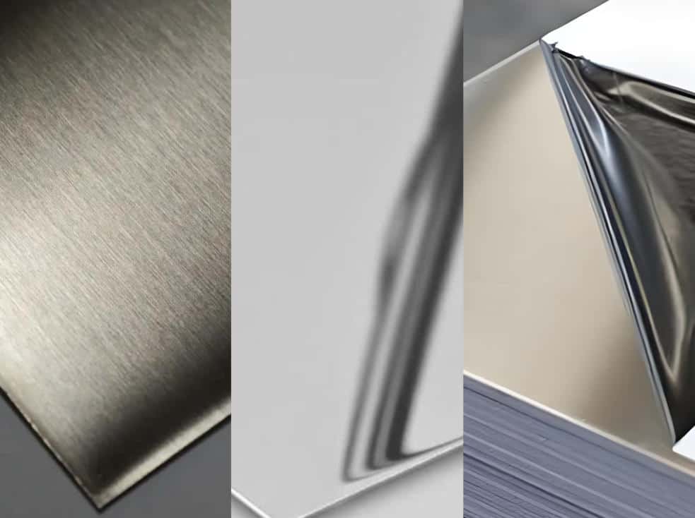
2B, BA, brushed, mirror-polished, and coated stainless steel all have different surface quality requirements.
The higher the surface grade, the more necessary it is to use non-marking tooling or interlayer film solutions. For mirror-polished stainless steel with extremely high surface requirements, the focus of the bending process must be on ensuring the surface remains scratch-free.
Part requirements
Before bending, we must clearly define the part requirements. These include angle tolerances, flange dimensions, inside radius, surface finish requirements, and batch consistency requirements. These specifications directly determine the processes and machine configurations required.
Engineering guide to estimating stainless steel bending tonnage
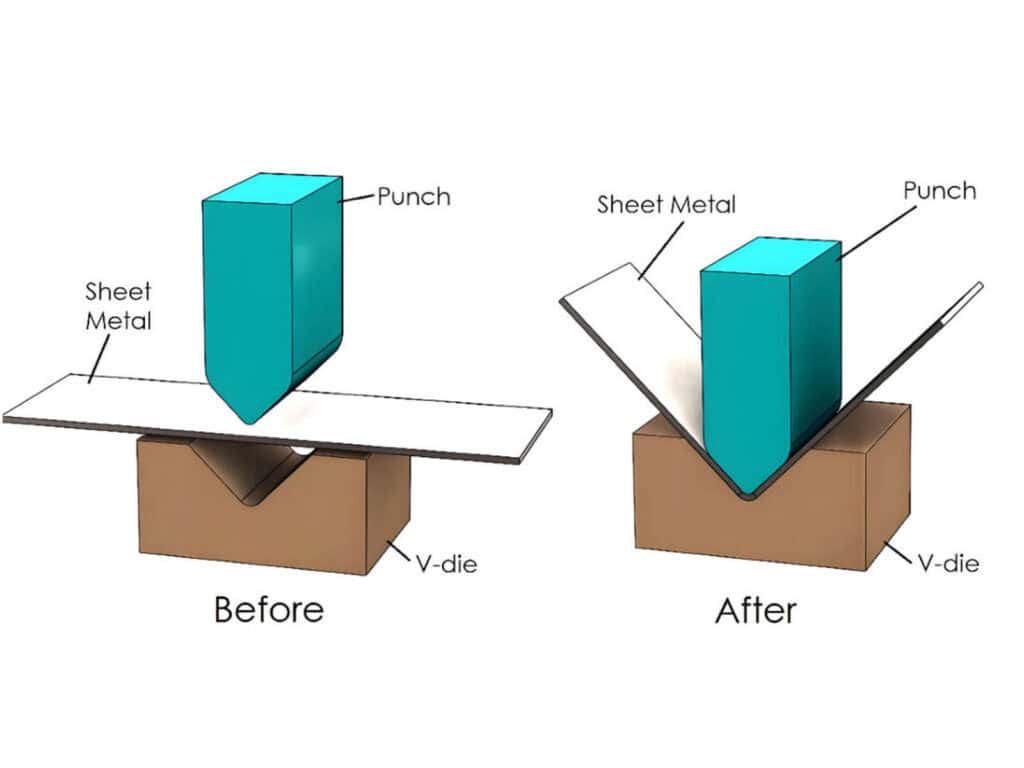
What is press brake tonnage?
The bending force required when the punch presses the metal sheet into the lower die to produce plastic deformation.
How should the standard formula be interpreted?
A common formula for estimating tonnage is:
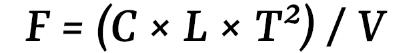
The primary purpose of providing this formula is not to require manual calculations, but to help us understand the relationships between the various parameters:
It is important to note that this type of formula is primarily suitable for preliminary estimates in air bending processes. If bottoming or coining processes are used, the tonnage required by the press brake will be significantly higher; therefore, the same set of empirical values cannot be directly applied. ( Related technical reading: Air Bending vs Bottom Bending vs Coining )
Why is stainless steel typically estimated using a higher coefficient?
Because the yield strength and work hardening characteristics of stainless steel (especially common austenitic stainless steel) are generally significantly higher than those of mild steel, the bending force required is often greater under the same plate thickness, length, and V-die conditions.
If we define the formula as follows:
Then, the standard calculation method for ordinary mild steel in the engineering industry is:
Mild steel (low-carbon steel): C ≈ 650
For 304 stainless steel, many sites will initially use approximately 1.4–1.5 times the result for ordinary mild steel as a preliminary estimate. According to publicly available data, the strength of mild steel is approximately 60,000 PSI, while that of 304 stainless steel is approximately 84,000 PSI. Based on this ratio, the coefficient for 304 stainless steel is approximately 1.4; if a company’s internal processes are more conservative, a multiplier of 1.5 is often used as the starting point for estimation. (RAYMAXTECH also recommends using a coefficient of 1.5.)
Therefore, within this formula system, it can be understood as follows:
Where:
Note: This is merely an empirical starting point for preliminary estimation and cannot be directly applied in actual production. The final tonnage must be calculated based on material condition, V-die dimensions, target inside radius (R), bending length, equipment rigidity, and test bending results.
Six variables affecting bending tonnage
The bending tonnage for stainless steel is influenced by six variables: material grade and strength, sheet thickness, bend length, V-die opening dimensions, bending process, and target inside radius.
Recommended Tonnage Comparison Table for Mild Steel and Stainless Steel Bending (Based on Standard V = 8T and Air Bending)
To facilitate a quicker initial assessment, the table below compares the reference tonnage values for standard mild steel and 304 stainless steel based on the air bending process and the condition that the V-die opening equals 8T. However, this should only be used as a preliminary estimate and cannot be treated as a fixed value for final production.
|
plate thickness |
Mild Steel Reference Tonnage (tons/m) |
304 Stainless Steel Reference Tonnage (tons/m) |
Notes |
|---|---|---|---|
|
1mm |
≈8 |
≈12 |
Thin sheets exhibit significant springback; pay close attention to angle compensation. |
|
2mm |
≈17 |
≈25 |
The bending force required for 304 stainless steel is significantly higher than that for ordinary steel. |
|
3mm |
≈25 |
≈37 |
We recommend paying close attention to equipment rigidity and V-die compatibility. |
|
5mm |
≈42 |
≈62 |
For thick sheet projects, focus on inside radii, V-die, and the risk of cracking. |
Practical example
Example 1:
Suppose we are bending a 1-meter-long, 2-mm-thick piece of 304 stainless steel, assuming air bending, with C ≈ 975 for 304 stainless steel and a common V-die range of 8T–12T, the theoretical bending force is approximately 16.6–24.9 tons.
Under these conditions, although this estimate suggests that such workpieces do not require a very high tonnage, we typically do not base our selection solely on the estimated value when actually selecting equipment. Factors such as equipment margin, tooling compatibility, batch consistency, and room for subsequent process adjustments must also be considered.
Common selection approaches include:
Example 2:
However, if you need to bend a 2.5-meter-long, 2mm-thick 304 stainless steel workpiece under the same conditions, the theoretical bending force would increase to approximately 41.5–62.2 tons.
In this case, although the theoretical force is still not particularly excessive, due to the significant increase in workpiece length, equipment selection cannot be based solely on bending force; factors such as effective working length, frame rigidity, crowning capability, back gauge accuracy, and support capacity for long workpieces must also be considered.
Therefore, the most common approach for such applications is typically:
Summary: the above two examples illustrate that even for 2mm-thick 304 stainless steel, different bending lengths result in significantly different equipment selection strategies.
Common procurement misconceptions
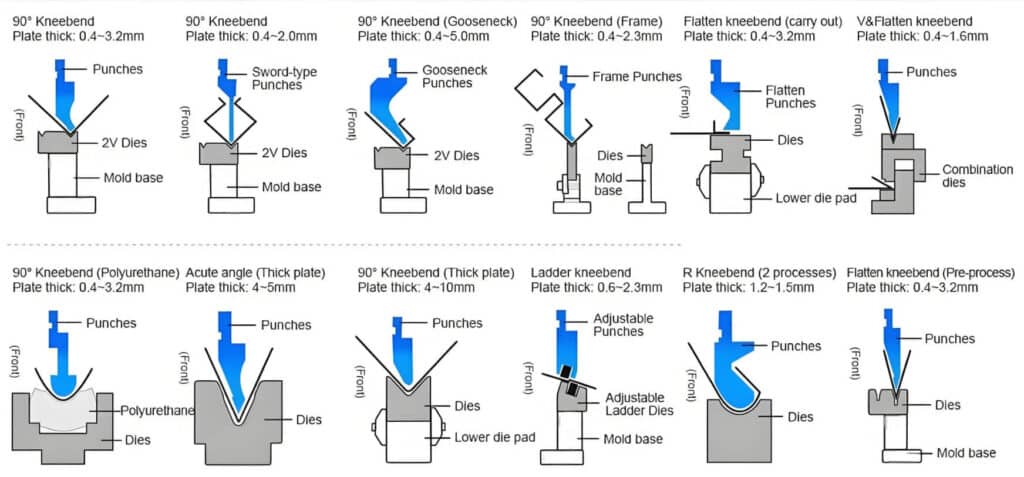
How should I choose a V-die and an upper punch?
The fundamental principles of V-die selection
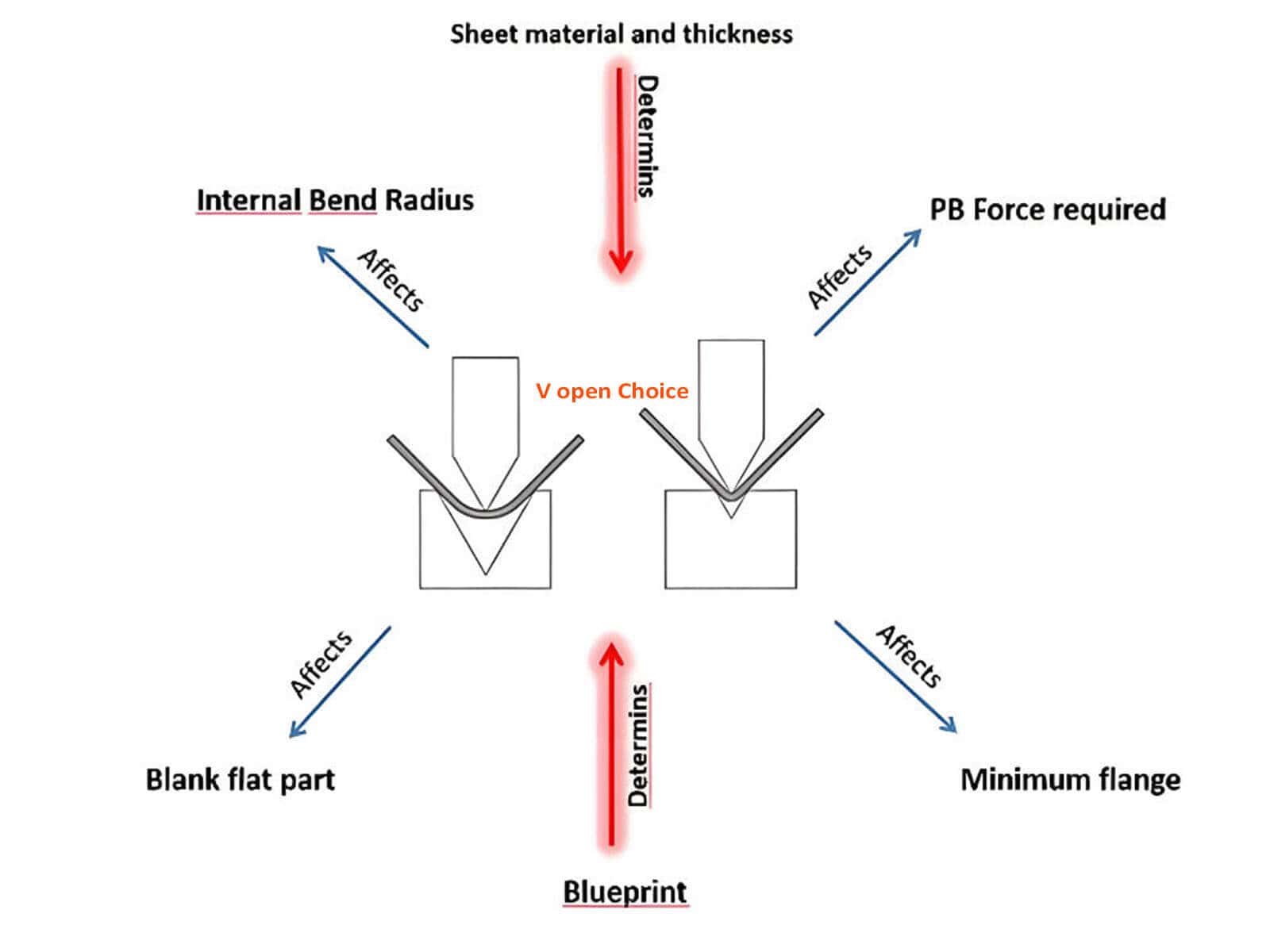
The V-die is by no means chosen arbitrarily; its width determines the required tonnage, the size of the formed fillet radius, the degree of springback, and the depth of the indentation left by the tooling on the sheet surface. The width of the V-die should be selected within the permissible range.
Generally speaking:
Engineering rationale for the 8T–10T starting point
In air bending applications, the industry generally recommends using a V-die opening width of 8T–10T as a starting point for stainless steel. The purpose is to reduce tooling load and minimize surface indentations on the stainless steel.
For thick sheets, situations with a high risk of cracking, or when high aesthetic standards are required, small V-die should not be used indiscriminately.
What happens if the V-die is too small?
If the V-die is too small, the tonnage required by the equipment increases rapidly, and the load on the tooling also increases. This can result in deeper indentations on the material surface and, in severe cases, cause cracks on the outer surface of the material due to excessive stretching.
What happens if the V-die is too large?
If the V-die is too large, material springback becomes difficult to control, making it hard to maintain the desired bend angle. It also causes the inside radius to increase. When bending workpieces with short flanges, the flange edge may slip directly into the V-die, preventing the bend from being formed.
Stainless steel V-die quick reference chart
|
Plate Thickness |
≤2mm |
3-4mm |
≥5mm |
|---|---|---|---|
|
Recommended V-die starting point |
8T |
8T-10T |
10T-12T |
|
Recommended for high surface finish requirements |
10T+ protective film |
10T-12T |
≥12T |
|
Recommended when there is a high risk of cracking |
10T+ stretch-resistant |
12T+ with enlarged R-corner transitions |
12T-14T |
|
Remarks |
Requires balancing V-die and short-edge requirements |
Pay close attention to the springback angle |
The risk of cracking is extremely high; the V-die must be enlarged. |
Why shouldn’t the upper punch tip radius be too small?
When the upper punch tip radius is too small, the contact area between the upper punch and the material is very small, resulting in high pressure. During the downward stroke, it will pierce directly into the material like a knife blade, causing severe tensile stress on the outer surface of the material and leading to cracking. This is particularly critical for high-strength stainless steel. Therefore, we should select an appropriate upper punch tip radius based on the sheet thickness, material properties, and required inside radius.
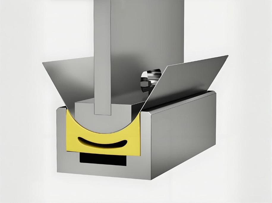
What else should be considered for molds used on high-surface-finish parts?
It is also necessary to inspect the surface finish of the mold, checking whether the contact edges have been polished and whether there are any burrs. The mold design should also facilitate the use of mark-free protection solutions, such as mark-free film and polyurethane pads.
Controlling springback: taming stainless steel’s “memory”
The nature of springback
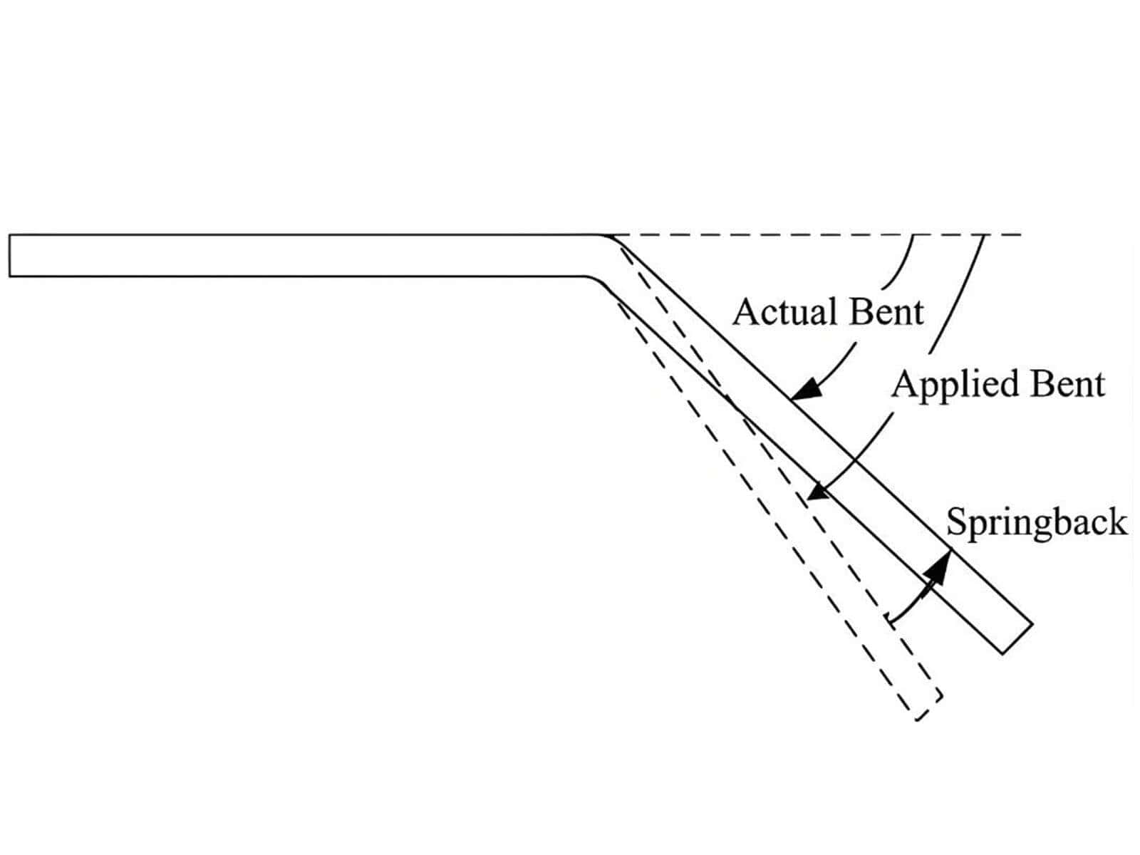
Springback refers to the elastic recovery of metal sheets after the removal of pressure, caused by the release of internal stresses within the material, resulting in a slight opening of the angle.
Why does springback occur more pronouncedly in stainless steel?
Because stainless steel (especially austenitic stainless steel) has a very high yield strength, its elastic recovery is more pronounced. For 304 and 316 stainless steel, the empirical range of springback is estimated to be between 2° and 5°. However, this is not a fixed value and is also influenced by the manufacturing process.
Key factors affecting springback
Material hardness, sheet thickness, rolling direction, bending angle, V-die width, and bending method can all influence material springback.
How to interpret common empirical springback ranges in the field?
Although we often use 2° to 5° as the common empirical range for 304 and 316 stainless steel, this cannot be treated as a fixed value; the actual springback angle varies with changes in material condition, sheet thickness, tooling, angle, and process.
For example, if we switch to a batch of material with slightly higher hardness or use a V-die with a slightly wider opening, the springback angle may immediately change from 3° to 5°.
Four methods of springback control
Overbending:
This is the most commonly used method. Since material springback causes the actual angle to be slightly larger than the intended angle, we intentionally bend to a slightly smaller inside angle than the target angle. For example, if our target inside angle is 90°, and the material is expected to spring back by 2°, we can set the bending program to 88°. This way, after the pressure is released, the final angle after springback will be exactly 90°.
When using overbending, do not blindly overcompensate; establish the compensation value based on trial bends.
A Brief Dwell at Bottom Dead Center:
When the upper punch reaches its deepest point (the lower dead center), pause briefly—for example, for a fraction of a second. This allows internal stresses in the material to flow and redistribute fully, which can improve angle consistency under certain conditions. However, this method should not be overemphasized, as the final result is still influenced by the material and process.
CNC compensation and material database:
Modern CNC press brake systems and their built-in material databases are particularly important for mass production. By entering the material grade and thickness into the system, it automatically calculates compensation values and performs springback compensation. For processing long workpieces, crowning must also be considered in conjunction with this.
Optimizing the V-die:
Within permissible limits, selecting a V-die with a smaller opening width can help reduce springback. However, the selection range must be carefully controlled; if the V-die is too small, the required tonnage will increase, potentially raising the risk of cracking or indentations.
On-site issue: Why does the angle become inaccurate when switching to a new batch of material?
Possible causes include: Differences in heat treatment between material batches, which may result in variations in hardness. Alternatively, there may be slight deviations in sheet thickness. It could also be due to mold wear, causing the angle to be inaccurate.
How can you prevent dents, scratches, and scuff marks on stainless steel surfaces?
Why are surface defects in stainless steel more critical than angular defects?
Because stainless steel is often used for high-end exterior components, its surface quality requirements are extremely stringent. During the bending process, even if the angles and dimensions of the stainless steel meet specifications, any scratches or indentations on the surface may be irreparable, resulting in the part being scrapped.
List of common surface defects
Common surface issues in stainless steel bending include: indentations, scratches, drag marks, bright spots, die adhesion, damage to the brushed finish, and damage to the protective film.
Common protection methods
Why is “adding just one layer of film” not always sufficient?
This is because surface damage to the sheet may not only occur during the process of pressing the sheet into the lower die, but may also result from other causes, such as: burrs on the tooling edges, scratches caused by the sheet sliding on the worktable, and drag marks caused by friction between long workpieces and the tooling or worktable during loading, unloading, or flipping.
304 vs. 316: Should they be treated differently during bending?
Why do buyers always ask about 304 and 316 separately?
When bending stainless steel, we must consider multiple factors, including cost, strength, corrosion resistance, springback, surface risks, and whether higher-spec machinery is required.
Since 316 is significantly more expensive than 304 and offers superior corrosion resistance, buyers worry that it might make forming extremely difficult, make springback harder to control, increase the risk of cracking, and necessitate the purchase of a more powerful press brake.
How should 304 and 316 be understood from a bending perspective?
Both 304 and 316 are common austenitic stainless steels and may exhibit noticeable springback. However, in actual operation, factors such as grade, hardness, sheet thickness, and batch can also influence the actual process performance.Because 316 stainless steel is often more expensive, its bending projects are usually handled more cautiously, and decisions should not be based on experience alone. You can click on “304 vs 316 stainless steel bending force” to learn more about this technical aspect.
Under what circumstances is a test bend verification required?
Test bend verification is mandatory when working with parts that have small inside radius, long workpieces, extremely narrow flanges, high-volume continuous production, parts with high aesthetic requirements, or complex parts requiring multiple bends.
What kind of press brake is truly suitable for stainless steel?
Selection criteria
A press brake that is truly suitable for stainless steel must not only be capable of bending, but also capable of producing high-quality parts in large quantities over the long term with consistent reliability.
Eight key technical considerations for equipment selection:
For stainless steel projects, what questions should customers ask manufacturers when making an inquiry?
Common issues and troubleshooting tips for stainless steel bending
The tonnage seems sufficient, but the bend angle is still unstable.
First part is accurate, but subsequent parts begin to deviate
Visible indentations on the surface
Inconsistent angles in the middle of long panels
The machine becomes inaccurate after switching to a new batch of material
Narrow edges are prone to deformation
Mirror-finished parts are frequently scratched
Small-radius bends always crack
Protective film damage after bending film-coated sheet metal
Low batch yield for stainless steel parts
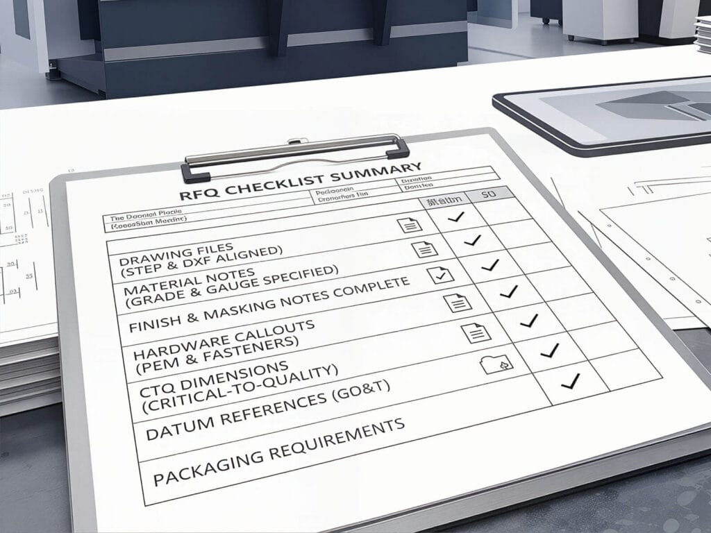
What information should you prepare before making an inquiry?
Minimum of 7 pieces of information
To obtain the most suitable press brake and configuration, please provide the following 7 pieces of information when submitting an inquiry:
Material grade, thickness range, maximum bending length, estimated daily/annual production volume, surface finish requirements, typical part drawings, and tolerance requirements for critical angles and dimensions.
Why is this information necessary?
The more detailed the information provided, the more suitable the configuration the manufacturer can recommend.
How does a professional manufacturer respond?
A truly professional manufacturer, upon reviewing the information provided by the customer, will typically discuss the workpiece and process first, and only then recommend suitable press brake models and configurations. They will provide recommendations tailored to the customer’s requirements, including tonnage suggestions, test bending recommendations, tooling selection advice, compensation strategies, and surface protection strategies.
Conclusion
The challenges of bending stainless steel lie in four key areas: higher forming force requirements, difficult-to-control springback, strict tolerance requirements, and extremely high aesthetic standards.
To master stainless steel bending with ease, we need to: select the appropriate tonnage, choose the correct tooling, set precise springback and crowning, implement surface protection measures, and select highly rigid equipment.
If you are still struggling with high defect rates in stainless steel bending, or if you are looking for a high-rigidity press brake capable of handling stainless steel bending, please feel free to send us your part drawings and specifications. Raymax will provide you with a free tonnage assessment, tooling recommendations, and machine configuration proposals.
Ready To Upgrade Your Metal Fabrication Line?
Email Us For A Free Consultation.
Frequently Asked Questions (FAQs)
Related Blog

Proper setup steps for Press brakes and analysis of common calibration issues
Press Brake Overview and Smart Selection Tips
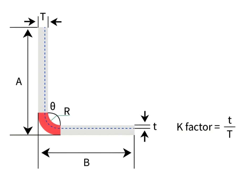
Bend Allowance vs Bend Deduction vs K-Factor: How to Calculate Sheet Metal Flat Patterns (With Examples)
-1024x768.jpg)
10 Common Press Brake Air Bending Problems: Causes, Troubleshooting, and Fixes

Press Brake Clamping System Guide:Types,Tooling Compatibility&Faster Tool Changeovers
Press Brake Fundamentals: Types, Components, Working Principle, Safety & Maintenance
Press Brake for Automotive Sheet Metal Parts: Springback Control, Mark-Free Tooling & Hemming
Press Brake for Elevator Panels: How to Achieve No-Mark Bending & Perfect Long-Panel Angle Consistency
Press Brake Tooling Guide: Punches, Dies, Types and Selection
Press Brake Quick Clamping System: Types, Compatibility & How to Choose (Quick Clamp Guide)
How to Spec a Press Brake for Tolerance: Angle, Flange Length, Crowning, Backgauge & Acceptance Checklist
V-Die Opening Rule (6t/8t/10t): How to Choose Die V for Accurate Bending
Post Your Review
Share Your Thoughts And Feelings With Others