
Francis Pan
Francis Pan is the Foreign Trade Manager of RAYMAX, with over 10 years of experience in sheet metal fabrication equipment and CNC machinery. He has worked closely with manufacturers worldwide on press brakes, fiber laser cutting machines, fiber laser welding machines, and practical production-oriented metal processing solutions.
Top Guidelines
-1024x768.jpg)
-1024x768.jpg)
-1024x768.jpg)
-1024x768.jpg)
Table Of Contents
Stay in the the loop
Subscribe To Our Newsletter
Introduction
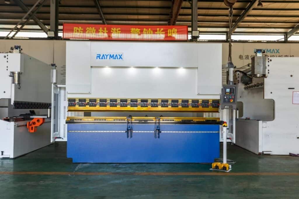
In the field of metal processing, press brake and metal material thickness are two concepts. As a mechanical press, press brake bending machine is mainly responsible for the bending and forming of metal sheets. Metal material thickness, that is, the vertical thickness of metal sheets, is a key parameter that affects processes such as bending, cutting, and forming.
Metal material thickness is directly related to the selection and bending performance of the brake press. Metals of different thicknesses require press brakes of different models and performances to handle, which will also affect the bending process and final effect. Understanding the significance of common metals and their thickness levels to the process, mastering bending tonnage calculations, process parameters, and on-site solutions are essential to improving the efficiency and quality of metal processing.
This article aims to help manufacturing personnel gain an in-depth understanding of the impact of different metal material thicknesses on bending operations, so that they can make more reasonable decisions when selecting and configuring press brakes, thereby improving production efficiency and product quality.
Basic knowledge of press brake metal material thickness
The importance of metal material thickness to the selection of press brakes
Material thickness plays a decisive role in choosing the right brake press and press brake tool. Thicker materials require higher tonnage press brakes. If you choose a low-tonnage brake press, it will not only damage the machine and increase maintenance costs, but also affect the uniform and accurate bending effect of the material.
Common units of metal material thickness (mm and inch)
In the industry, the commonly used units for measuring metal material thickness are millimeters (mm) and inches (inch). Millimeters are widely used in most Asian and European factories, while the imperial unit inch is more common in North America. The conversion relationship between them is 1 inch = 25.4 mm. In addition, in addition to feet, the United States also often uses Gauge (American Standard) to indicate metal material thickness. In practical applications, these counting units usually need to be converted.
General classification of metal material thickness and its industry standards
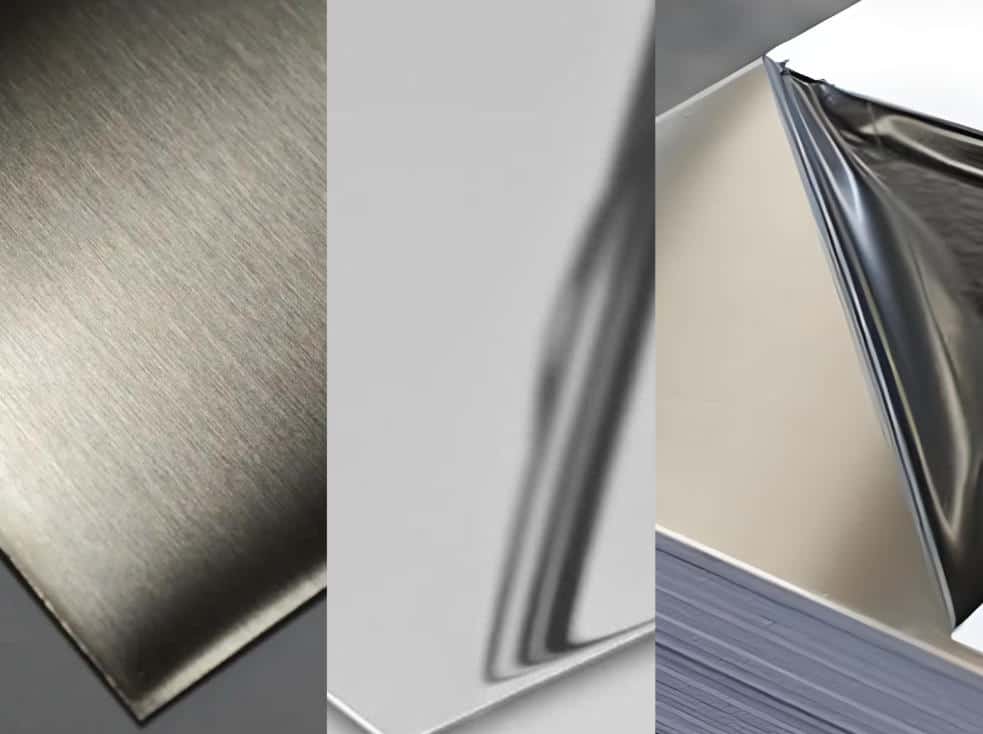
Common metals and their typical thickness ranges
Carbon steel
Carbon steel has the largest thickness range among common metals, with a common thickness of 0.5-20mm. Thanks to its large thickness and high hardness, carbon steel is very popular in large-scale manufacturing fields such as automobiles and engineering, and adopts the GB/T709 standard;
Stainless steel
The general thickness is 0.5-12 mm. This material is thinner than carbon steel, and is very corrosion-resistant and hygienic. It is used in the kitchen, medical, decoration and other industries, which conforms to people’s aesthetics and hygiene. The ASTM A240 standard is used.
Aluminum plate
Aluminum is lighter than other corrosion-resistant metals, with an average thickness of only 0.5-10mm. Its “small weight” is the only choice for electronic housings, aviation parts, etc. The corresponding standard is GB/T3880.
Copper
The conventional thickness is 0.5-5mm, and its thermal and electrical conductivity are excellent, and it has a metallic luster, so it is mostly used for conductive parts, decorative parts, etc., and the reference is GB/T2059 standard.
Standard Sheet Thickness Lookup Chart
|
Material Name |
Available Gauge Thickness, Inch. |
|---|---|
|
Aluminum 2024-T3 |
0.025” |
|
Aluminum 5052 H32 |
0.020”, 0.025”, 0.032”, 0.040”,0.050”, 0.063”, 0.080”, 0.090”, 0.100”, 0.125”, 0.160”, 0.188”, 0.250”, 0.375”, 0.500” |
|
Aluminum 6061 T6 |
0.016”, 0.020”, 0.025”, 0.032”, 0.040”, 0.050”, 0.063”, 0.080”, 0.090”, 0.100”, 0.125”, 0.160”, 0.190”, 0.250”, 0.313”, 0.375”, 0.500”, 0.625”, 0.750”, 0.750”, 0.875”, 1.000” |
|
Aluminum 7075 T6 |
0.025”, 0.032”, .040”, 0.050”, 0.063”, 0.071”, 0.080”, 0.090”, 0.100”, 0.125”, 0.160”, 0.190”, 0.250”, 0.375”, 0.500”, 0.625”, 0.750”, 1.000” |
|
Aluminum MIC6 |
0.250”, 0.375”, 0.500”, 0.750” |
|
Pre-Anodized 6061-T6, Black |
0.063”, 0.125”, 0.250”, 0.375”, 0.500” |
|
Brass 260 |
0.005”, 0.010”, 0.016”, 0.020”, 0.025”, 0.032”, 0.040”, 0.050”, 0.063”, 0.080”, 0.093”, 0.125”, 0.188”, 0.250” |
|
Brass 353 H02 |
0.063”, 0.125”, 0.150” |
|
Brass 464 H01 |
0.032”, 0.040”, 0.063”, 0.080” |
|
Bearing Bronze 932 M07 |
0.250” |
|
Bronze 220 H02 |
0.020”, 0.032”, 0.040”, 0.050”, 0.064”, 0.080”, 0.090”, 0.125” |
|
Bronze 510 H08 (spring) |
0.005”, 0.008”, 0.010”, 0.016”, 0.020”, 0.032”, 0.040”, 0.050”, 0.064”, 0.090”, 0.125” |
|
Silicon Bronze 655 |
0.063” |
|
Copper 101, H00 to H01 |
0.025”, 0.032”, 0.040”, 0.050”, 0.063” |
|
Copper 110, Annealed |
0.005”, 0.010”, 0.021”, 0.043”, 0.063”, 0.093”, 0.125” |
|
Copper 110, H01 |
0.016” |
|
Copper 110, H02 |
0.020”, 0.040”, 0.050”, 0.063”, 0.080”, 0.093”, 0.125”, 0.188”, 0.250” |
|
Nickel 200, annealed |
0.019”, 0.062” |
|
Nickel 625, annealed |
0.020”, 0.032”, 0.040”, 0.050”, 0.063” |
|
Stainless Steel 17-4 PH, annealed |
0.018”, 0.032”, 0.040” |
|
Stainless Steel 17-7 shim, hardened |
0.004”, 0.005”, 0.010”, 0.020”, 0.031” |
|
Stainless Steel 301, spring temper |
0.005”, 0.006”, 0.010”, 0.012”, 0.015”, 0.018”, 0.020”, 0.031”, 0.042”, 0.048”, 0.059” |
|
Stainless Steel 304 |
0.018”, 0.024”, 0.030”, 0.036”, 0.048”, 0.060”, 0.075”, 0.105”, 0.120”, 0.188”, 0.250”, 0.313”, 0.375”, 0.500”, 0.625”, 0.750”, 1.000” |
|
Stainless Steel 304 shim, hardened |
0.005”, 0.006”, 0.010”, 0.012”, 0.015”, 0.020”, 0.025” |
|
Stainless Steel 304, #4 brushed |
0.024”, 0.036”, 0.048”, 0.060”, 0.075”, 0.090”, 0.120”, 0.135”, 0.250”, 0.375”, 0.500”, 0.625” |
|
Stainless Steel 316 |
0.018”, 0.024”, 0.030”, 0.036”, 0.048”, 0.060”, 0.075”, 0.105”, 0.120”, 0.135”, 0.188”, 0.250”, 0.313”, 0.375”, 0.500”, 0.625”, 0.750”, 1.000” |
|
Stainless Steel 410, annealed |
0.250” |
|
Stainless Steel 430, #3 brushed |
0.035”, 0.046”, 0.060” |
|
Stainless Steel 440C |
0.063”, 0.094”, 0.125”, 0.156”, 0.188” |
|
Stainless Steel CPM 154 |
0.063”, 0.094”, 0.125”, 0.156”, |
|
Stainless Steel S30V, annealed |
0.094”, 0.125”, 0.188”, 0.250” |
|
1075 Spring Steel, annealed |
0.050”, 0.188” |
|
1075 Spring Steel, Blue Tempered |
0.015” |
|
1095 Spring Steel, annealed |
0.015”, 0.025”, 0.035”, 0.050”, 0.063”, 0.083”, 0.125”, 0.188” |
|
1095 Spring Steel, blue tempered |
0.005”, 0.008”, 0.010”, 0.015”, 0.020”, 0.025”, 0.030”, 0.035”, 0.042”, 0.050”, 0.063” |
|
4130 chrome-moly steel, annealed |
0.032”, 0.040”, 0.050”, 0.063”, 0.080”, 0.100”, 0.125”, 0.160”, 0.190”, 0.250” |
|
AR400 Steel, hardened |
0.125”, 0.188”, 0.250”, 0.375”, 0.500” |
|
AR500 Steel, hardened |
0.119”, 0.188”, 0.250”, 0.375”, 0.500”, 0.625”, 0.750” |
|
Corten A588 (Weathered) Steel |
0.060”, 0.075”, 0.100”, 0.120”, 0.135”, 0.188”, 0.250” |
|
Hot Rolled Steel 1045 |
0.250”, 0.375”, 0.500”, 0.625”, 0.750”, 1.000” |
|
Hot Rolled Steel A569/ASTM A1011 |
0.060”, 0.075”, 0.105”, 0.125”, 0.135” |
|
Steel 1008, zinc-galvanized |
0.024”, 0.033”, 0.048”, 0.060”, 0.075”, 0.100”, 0.120”, 0.135” |
|
Steel 1018 |
0.125”, 0.188”, 0.250”, 0.313”, 0.375”, 0.500”, 0.625”, 0.750”, 0.875”, 1.000” |
|
Steel 4140, hardened |
0.125”, 0.188”, 0.250”, 0.375”, 0.500” |
|
Steel 80CRV2 |
0.125”, 0.188” |
|
Steel A36 |
0.100”, 0.120”, 0.188”, 0.250”, 0.313”, 0.375”, 0.500”, 0.625”, 0.750”, 1.000” |
|
Steel A36, pickled and oiled |
0.060”, 0.075”, 0.100”, 0.120”, 0.135”, 0.135”, 0.188”, 0.250”, 0.375”, 0.500” |
|
Steel A366/1008 |
0.024”, 0.030”, 0.036”, 0.048”, 0.060”, 0.075”, 0.090”, 0.105”, 0.125” |
|
Steel A572 Grade 50 |
0.188”, 0.250”, 0.313”, 0.375”, 0.500” |
|
Steel G90, galvanized |
0.022”, 0.024”, 0.033”, 0.048”, 0.060” |
|
Tool Steel D2, annealed |
0.063”, 0.094”, 0.125”, 0.156”, 0.188” |
|
Tool Steel O1, annealed |
0.016”, 0.031”, 0.047”, 0.063”, 0.078”, 0.094”, 0.109”, 0.125”, 0.156”, 0.188”, 0.250”, 0.313”, 0.375”, 0.438”, 0.500” |
|
Titanium (Grade 2) |
0.035” |
|
Titanium 6Al-4V (Grade 5) |
0.032”, 0.063”, 0.125”, 0.188”, 0.250” |
Sheet thickness lookup chart for sheet cutting or forming processes. These are the standard available thicknesses of the listed material; other thicknesses may be available upon request. RAYMAX uses thickness measurements instead of sheet gauges.
How to choose the appropriate metal material thickness of the press brake
The influence of material type on the thickness of the bending metal
Different materials have different characteristics, and their tensile strength, ductility, yield strength and plasticity are different. For example, the yield strength of standard Q235 steel is about 235MPa. For materials, the stronger the characteristics, the greater the required bending force.
Note: Table of tensile strength range of common metallic materials
|
Material |
Tensile strength range (MPa) |
Description |
|
Low carbon steel (mild steel) |
300 – 500 |
Common building and structural materials |
|
Medium carbon steel |
600 – 800 |
Used for mechanical parts |
|
High carbon steel |
800 – 1200 |
High hardness and strength |
|
Stainless steel |
520 – 1250 |
Corrosion-resistant, widely used |
|
Aluminum alloy |
200 – 600 |
Lightweight, easy to form |
|
Brass |
300 – 900 |
Good corrosion resistance |
|
Titanium alloy |
700 – 1200 |
Lightweight and high strength, good corrosion resistance |
|
Magnesium alloy |
200 – 350 |
Extremely light, but low tensile strength |
Relationship between metal material thickness and bending radius
According to experience, the bending radius should be controlled to 1 to 1.5 times the material thickness, which can ensure that the material is prevented from cracking or damage, thereby ensuring a good folding effect. A larger thickness requires a larger radius. For example, 3mm stainless steel is recommended to be no less than 6mm.
press Brake Tonnage and capacity
The tonnage of the brake press determines the upper limit of the force that can be applied, which directly determines the maximum metal material thickness that can be bent. The general tonnage calculation formula is:
Tonnage=L×T×(YieldStrength×K)Tonnage=L×T×(YieldStrength×K).
Where L is the bending length, T is the metal material thickness, and K is determined according to the material characteristics. It is not that the larger the tonnage, the better. To ensure the accuracy of large and thick parts, the tonnage of the brake press bending machine is generally required to be proportional to the thickness.
press brake Die Selection and V-Die Opening Specifications
If the V opening is too narrow, the workpiece is more likely to crack; if it is too wide, springback may increase. For hard materials, choose a suitable V-die material and opening width to reduce die wear. When selecting a V-die for bending, the V-opening width should usually be controlled at approximately 8 to 10 times the material thickness, and the die length should not be less than the maximum bending length of the workpiece.
For air bending applications, the relationship between material thickness, V-opening width, punch depth, and springback is especially important. You can also read our complete guide to press brake air bending to understand how these parameters affect bending accuracy and process stability.
Note: V-Die Sizing Table (Using Rule of Eight)
| Width of V-Die Opening | Thickness of Metal | |||||||||||||||||||||
| 26Ga .018″ | 24Ga .024″ | 22Ga .030″ | 20Ga .036″ | 18Ga .048″ | 16Ga .060″ | 14Ga .075″ | 13Ga .090″ | 12Ga .105″ | 11Ga .120″ | 10Ga .135″ | 9 Ga .149″ | 7Ga .187″ | 1/4 .250″ | 5/16 .313″ | 3/8 .375″ | 7/16 .437 | 1/2 .500″ | 5/8 .625″ | 3/4 .750″ | 7/8 .875″ | 1″ | |
| 1/8″ | 1.2 | 2.1 | 3.6 | . | . | . | . | . | . | . | . | . | . | . | . | . | . | . | Need Die Opening 10X material thickness | |||
| 3/16″ | 0.8 | 1.4 | 4.1 | . | . | . | . | . | . | . | . | . | . | . | . | . | . | . | ||||
| 1/4″ | 0.5 | 1.1 | 1.8 | 2.9 | 5.4 | . | . | . | . | . | . | . | . | . | . | . | . | . | . | . | . | . |
| 5/16″ | . | 0.7 | 1.4 | 2.2 | 4.0 | 7.0 | . | . | . | . | . | . | . | . | . | . | . | . | . | . | . | . |
| 3/8″ | . | . | 1.0 | 1.7 | 2.9 | 5.6 | 8.8 | . | . | . | . | . | . | . | . | . | . | . | . | . | . | . |
| 1/2″ | . | . | . | 1.2 | 2.2 | 3.6 | 10.0 | . | . | . | . | . | . | . | . | . | . | . | . | . | . | . |
| 5/8″ | . | . | . | . | 1.6 | 2.7 | 4.5 | 6.8 | 10.1 | . | . | . | . | . | . | . | . | . | . | . | . | . |
| 3/4″ | . | . | . | . | 1.3 | 2.2 | 3.4 | 5.4 | 7.4 | 10.5 | . | . | . | . | . | . | . | . | . | . | . | . |
| 7/8″ | . | . | . | . | . | 1.7 | 3.0 | 4.3 | 6.3 | 8.8 | 11.3 | . | . | . | . | . | . | . | . | . | . | . |
| 1″ | . | . | . | . | . | 1.4 | 2.5 | 3.7 | 5.4 | 7.2 | 9.6 | 13.1 | . | . | . | . | . | . | . | . | . | . |
| 1 1/8″ | . | . | . | . | . | . | 2.1 | 3.3 | 4.4 | 6.2 | 8.4 | 11.9 | 16.4 | . | . | . | . | . | . | . | . | . |
| 1 1/4″ | . | . | . | . | . | . | 1.7 | 2.9 | 4.0 | 5.4 | 7.0 | 9.0 | 14.0 | 28.8 | . | . | . | . | . | . | . | . |
| 1 1/2″ | . | . | . | . | . | . | . | . | 3.2 | 4.3 | 5.6 | 6.7 | 11.2 | 22.0 | 38.0 | . | . | . | . | . | . | . |
| 2″ | . | . | . | . | . | . | . | . | . | 3.2 | 4.1 | 5.2 | 7.6 | 15.3 | 26.0 | 41.0 | . | . | . | . | . | . |
| 2 1/2″ | . | . | . | . | . | . | . | . | . | . | 2.4 | 3.5 | 5.8 | 11.5 | 19.2 | 29.9 | 45.2 | . | . | . | . | . |
| 3″ | . | . | . | . | . | . | . | . | . | . | . | 2.2 | 4.5 | 9.1 | 16.0 | 24.0 | 35.0 | 47.9 | . | . | . | . |
| 3 1/2″ | . | . | . | . | . | . | . | . | . | . | . | . | . | 7.5 | 12.5 | 19.4 | 28.0 | 39.0 | 69.5 | . | . | . |
| 4″ | . | . | . | . | . | . | . | . | . | . | . | . | . | 6.2 | 10.6 | 16.0 | 24.0 | 33.1 | 58.0 | 92.0 | . | . |
| 5″ | . | . | . | . | . | . | . | . | . | . | . | . | . | . | 7.6 | 12.3 | 17.0 | 24.0 | 42.2 | 69.0 | 104.0 | . |
| 6″ | . | . | . | . | . | . | . | . | . | . | . | . | . | . | . | 9.3 | 14.6 | 19.0 | 32.4 | 52.2 | 80.0 | 112.2 |
| 7″ | . | . | . | . | . | . | . | . | . | . | . | . | . | . | . | . | 11.1 | 15.6 | 26.0 | 42.2 | 63.0 | 90.2 |
| 8″ | . | . | . | . | . | . | . | . | . | . | . | . | . | . | . | . | . | 12.7 | 23.0 | 36.0 | 52.5 | 76.0 |
| 10″ | . | . | . | . | . | . | . | . | . | . | . | . | . | . | . | . | . | . | 16.5 | 27.0 | 39.4 | 56.2 |
| 12″ | . | . | . | . | . | . | . | . | . | . | . | . | . | . | . | . | . | . | . | 21.0 | 31.2 | 44.0 |
Recommended Metal material Thickness Range
To maintain the machine, ensure that the actual bending thickness of the material should not exceed 80% of the equipment’s calibrated limit before processing. Each brake press has its recommended metal material thickness range.
Calculation of metal material thickness and bending tonnage
Bending tonnage calculation formula
Calculating the relationship between metal material thickness and bending tonnage is a key step for processing materials.
Quick Reference Table (Mild Steel):
|
Thickness (mm) |
V-Opening (mm) |
Tonnage per meter |
|---|---|---|
|
6 mm |
48 mm |
~43 tons |
|
8 mm |
64 mm |
~57.5 tons |
|
10 mm |
80 mm |
~71.9 tons |
|
12 mm |
96 mm |
~86 tons |
Common problems and solutions when bending metals of different thicknesses
Bending angle compensation method
During the bending process, the bending angle of thick plates may be difficult to operate due to large springback. At this time, it is necessary to use electronic measurement tools to optimize the angle, and use pressure compensation, angle compensation devices,deflection compensation system, or take over-bending treatment (the pre-bending angle is 2-4° smaller than the target). With the development of press brakes, modern press brakes bending machine are more fully equipped with laser or mechanical angle detection closed-loop systems, deformation measurement modules, and dynamic pressure adjustment.
Practical strategies for adjusting pressure and speed
Thin plates and thick plates have different properties. Reasonable adjustment of pressure and speed can achieve the best effect and avoid deformation and cracks. Thin plates should appropriately reduce pressure and speed to reduce wrinkles and surface indentations; thick plates should be bent in sections multiple times to prevent material cracking.
Common problems: overbending, rebound, cracking, deformation, etc.
Preventive and corrective measures to improve bending quality
As an important part of factory production, the factory unit should calibrate the mold regularly and try to use imported high-strength mold steel to ensure stable pressure and smooth oil return of the hydraulic system. Relevant maintenance personnel must regularly check the mold wear and keep the mold surface smooth and clean. With the development of maintenance and prevention technology, more new technologies such as CNC compensation mechanism, intelligent angle monitoring, pressure sensor, etc. can be put into use.
Conclusion
The selection of metal material thickness and the configuration of the brake press are key links in the metal processing process. When selecting equipment, it is necessary not only to consider a certain margin for metal material thickness, but also to consider that different materials must match different parameters.
It is recommended that manufacturing personnel fully combine actual needs to choose suitable press brake manufacturers and services. In this regard, Raymax can provide one-stop project consultation and automation upgrade suggestions for various sheet metal material thickness applications. If you have relevant needs, please contact us for professional advice and solutions.
FAQ
Related Blog
Press Brake Tooling Compatibility Guide: Punch & Die Standards, Segmented Tools & Clamping Fit
Tooling & Clamping for High-Mix Production: Quick Clamp vs Hydraulic Clamp vs Manual Clamp ROI
Press Brake RFQ Checklist: 14 Fields You Must Provide for an Accurate Quote
-1-1024x768.jpg)
How to Spec a Press Brake for Tolerance: Angle, Flange Length, Crowning, Backgauge & Acceptance Checklist
-1024x768.jpg)
How to Improve Press Brake Bending Consistency: Causes, Checks & Solutions
-1024x768.jpg)
How to Measure Press Brake Bending Angle: Tools, Methods & Calibration Pitfalls
.jpg)
Stainless Steel Bending Force: 304 vs 316 (Correction Factors, Springback & V-Die Selection)
-1024x768.jpg)
Press Brake Tonnage Comparison: Air Bending vs Bottoming vs Coining (How Force Changes + Safety Margin)
Non-Marking Press Brake Bending: How to Prevent Scratches on Brushed, Mirror-Finish & Film-Protected Sheets
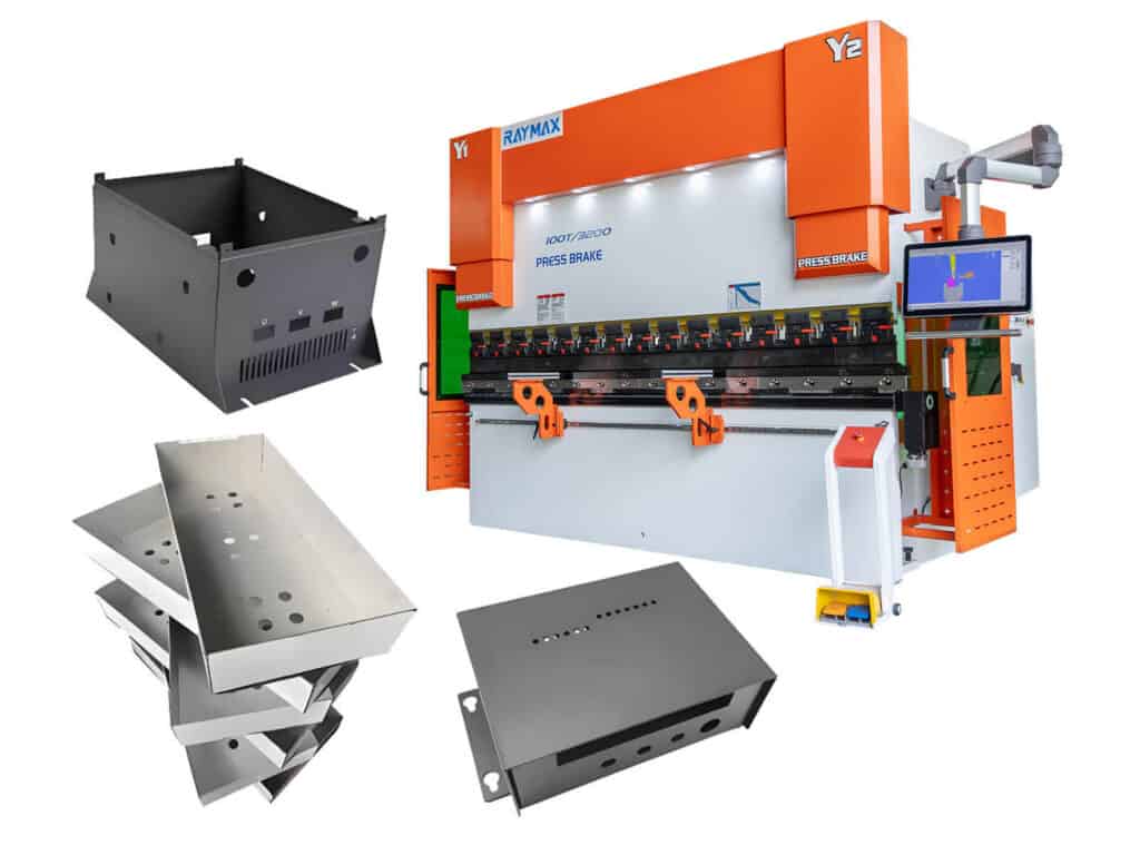
Electrical Enclosure Bending: Flat Pattern, Flange Accuracy & Fit-Up Issues

Press Brake Bending Accuracy Checklist: 10 Quantified Factors to Inspect
Press Brake for Stainless Steel: Tonnage, V-Die Selection, Springback & Surface Protection
Post Your Review
Share Your Thoughts And Feelings With Others