
Francis Pan
Francis Pan is the Foreign Trade Manager of RAYMAX, with over 10 years of experience in sheet metal fabrication equipment and CNC machinery. He has worked closely with manufacturers worldwide on press brakes, fiber laser cutting machines, fiber laser welding machines, and practical production-oriented metal processing solutions.
Top Guidelines
-1024x768.jpg)
-1024x768.jpg)
-1024x768.jpg)
-1024x768.jpg)
Table Of Contents
Stay in the the loop
Subscribe To Our Newsletter
Quick answer
When specifying a press brake for tolerance-critical parts, do not start with tonnage and working length alone. Start with bend angle tolerance, flange length tolerance, long-part consistency, repeatability, and batch stability, then work backward to the required machine configuration.
The correct approach to machine selection is not to judge by whether the first part passes inspection, but to verify whether the angle, flange length, and consistency across left, center, and right sides remain stable after the machine has produced 5–10 consecutive parts.
If you are selecting a CNC press brake machine for tolerance-critical parts, send your drawings, material specifications, sheet thickness, bend length, and tolerance requirements to Raymax. Raymax engineers can recommend the proper tonnage, backgauge, crowning system, tooling, and CNC configuration for your production needs.
Ready To Upgrade Your Metal Fabrication Line?
Email Us For A Free Consultation.
30-Second Assessment Chart—Which Category Does Your Part Fall Into?
The stricter the tolerance requirements, the more important it is during machine selection to look beyond whether the tonnage is sufficient. Instead, you must verify that the angle, flange length, and left-center-right consistency of the workpiece remain stable after 5–10 consecutive bends using the same bending program.
|
Drawing requirements |
Key considerations for machine selection |
Do not judge only by |
|---|---|---|
|
Standard brackets and enclosures: angle tolerance ±1° |
Basic CNC capabilities, appropriate tonnage, standard tooling |
Number of axes |
|
Electrical cabinets, boxes, and door panels: angle tolerance ±0.5° |
CNC backgauge, mechanical/CNC crowning system, stable tooling |
Controller brand |
|
Stainless steel exterior components: angle tolerance ±0.3°–±0.5° |
Springback compensation, tooling surface condition, non-marking tooling solutions |
Tonnage |
|
Workpieces 2–4 meters in length: consistent angles at the center and on both sides |
Frame rigidity, Y1/Y2 synchronization, crowning |
Short-part trial bends |
|
Multi-bend assemblies: flange tolerance ±0.2–0.3 mm |
Backgauge accuracy, gauging method, bending sequence |
Data from the first bend only |
|
Batch production of 500–1,000 units |
Repeatability, thermal stability, hydraulic stability, acceptance records |
Sample parts only |
Define part tolerances first, then discuss machine specifications
Classify tolerances into 5 categories
|
Tolerance type |
Meaning |
Key factors |
|---|---|---|
|
Bend angle tolerance |
For example, 90°, ±0.5° |
Y-axis depth, material springback, tooling, crowning |
|
Flange length tolerance |
For example, 50 mm, ±0.2 mm |
Backgauge X-axis, gauging method, workpiece edge quality, bending sequence |
|
Straightness of long workpieces |
Are the angles at the center and both ends of a long workpiece consistent? |
Frame rigidity, table deflection, crowning capability |
|
Repeatability |
When bending 10 pieces consecutively using the same program, are the angles and dimensions stable? |
Axis positioning accuracy, hydraulic system stability, tooling condition |
|
Batch consistency |
Is there any angle drift after continuous production? |
Oil temperature, material batch, tooling wear |
Since the control principles for these two factors differ, they must be evaluated separately during machine selection.
Tolerances Must Specify Measurement Conditions
When suppliers provide us with accuracy data, we must clarify the conditions under which this data was obtained.
|
Required specifications |
Why it matters |
|---|---|
|
Material grade |
Different materials have varying strengths, springback characteristics, and work hardening properties |
|
Sheet thickness |
Sheet thickness affects tonnage, inside bend radius, and springback |
|
Bend length |
The longer the workpiece, the more critical crowning becomes |
|
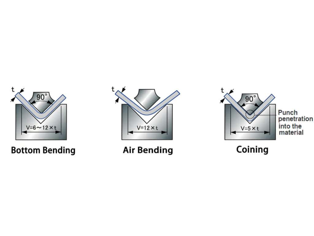
Bending method |
Air bending, bottoming, and coining exhibit different pressure requirements and springback behavior |
|
V-die opening |
The V-die opening affects tonnage, inside bend radius, minimum flange length, and indentation depth |
|
Measurement points |
A single-point pass does not guarantee consistency along the entire length |
|
Measuring tools |
Angle gauges, calipers, dial indicators, and CMMs have different measurement accuracies |
|
Batch specifications |
Data from the first part does not represent continuous batch data |
Tolerance Type × Influencing Factors × Configuration Requirements
|
Tolerance type |
Key factors |
Machine configuration requirements |
|---|---|---|
|
Bend angle tolerance |
Y-axis depth, material springback, tooling wear |
High repeatability on the Y-axis, stable hydraulic/servo system |
|
Flange length |
Backgauge X-axis, gauging method, workpiece edge quality |
High-stability backgauge, multi-axis backgauge |
|
Length consistency |
Frame deflection, table deformation |
Crowning system |
|
Batch repeatability |
Oil temperature, control system, material batch |
Stable hydraulic system, program reproducibility, acceptance testing |
|
Appearance tolerance |
Surface marks, protective film, material surface |
Non-marking tooling, protective film, appropriate V-die opening |
Proper selection involves establishing a one-to-one correspondence between tolerance types, influencing factors, and configuration requirements. If the approach to assessment or selection is incorrect, it becomes difficult to achieve the desired tolerance requirements.
How Accurate Can a Press Brake Be?
The precision of a press brake depends primarily on the machine’s rigidity, the backgauge, the compensation system, the tooling, the material, and the measurement methods.
Typical precision reference range
|
Accuracy grade |
Typical angular tolerances |
Typical flange length tolerances |
Applications |
|---|---|---|---|
|
Standard sheet metal |
±0.7°–±1.0° |
±0.5–1.0 mm |
Brackets, standard enclosures, non-critical structural components |
|
Precision sheet metal |
±0.3°–±0.5° |
±0.2–0.5 mm |
Electrical cabinets, electrical boxes, door panels, standard assemblies |
|
High-precision production |
±0.1°–±0.3° |
±0.1–0.2 mm |
Precision enclosures, continuous assemblies, parts requiring high consistency |
Please note that the data above is only a typical reference range for selection. The default conditions are: mild steel, air bending, standard sheet thickness (1–6 mm), precision-ground tooling, good calibration on the machine, and consistent material batches. It should not be considered a guaranteed value for any machine, material, or length.
Machine Positioning Accuracy ≠ Part Tolerance
Many people believe that high Y-axis positioning accuracy automatically ensures high bend angle accuracy, or that high backgauge repeatability guarantees precise final flange length. This is a common misconception in the industry.
Y-axis accuracy reflects the repeatability of the ram’s stopping position, but the final angle of the part is also affected by variations in thickness, material batch strength, and springback.
Similarly, backgauge repeatability reflects the stability of the backgauge positioning to the same target position over multiple cycles, but the final flange length is also influenced by the gauging method, workpiece edge quality, support method, and bending sequence.
Therefore, when purchasing equipment, we must clarify these four questions:
Only by clarifying these conditions can we understand the true part tolerances. Many buyers confuse axis repeatability with final part tolerance; this difference is explained in detail in our press brake repeatability vs accuracy guide.
How to Spec a Press Brake for Tolerance: Work Back from the Drawing
Correct Selection Process
Below is the complete process for configuring a press brake based on tolerances:
Configuration Differences for Different Tolerance Targets
Tonnage Determines Whether Bending Is Possible; Tolerances Determine Whether the Part Meets Specifications
Tonnage Calculations Must Clearly Specify Input Conditions
When calculating tonnage, the following conditions must be correctly inputted:
Tonnage estimation formula
The common tonnage estimation formula for air bending processes is:

In this formula:
This formula is only applicable for preliminary estimates in air bending processes; the actual tonnage will also be affected by fluctuations in material batch strength, the actual dimensions of the V-die opening, tooling condition, and process conditions. Therefore, the final tonnage must be verified in conjunction with the manufacturer’s actual operating conditions. If your process may shift from air bending toward bottoming or coining, review this press brake tonnage comparison before finalizing the machine capacity.
Worked Example—3 mm mild steel electrical cabinet door panel
The following demonstrates a complete configuration selection process for mild steel using the air bending process:
Step 1: Define the input conditions:
Step 2: Calculate the tonnage:
First, calculate the bending force per meter:
.jpg)
Next, calculate the total bending force:
.jpg)
Finally, add a 20% safety margin to estimate the required machine tonnage:
.jpg)
Step 3: We need to make the final selection decision:
|
Configuration options |
Recommended specifications |
|---|---|
|
Machine tonnage |
Calculated lower limit: approximately 52 tons; select a machine from the next higher tonnage range according to the manufacturer’s standards; do not select a machine that is too close to the lower limit |
|
Working length |
≥2500 mm (to cover a bending length of 2000 mm and allow for clamping clearance) |
|
Crowning system |
Include in the configuration evaluation; verify left-center-right angles for long parts. |
|
Backgauge |
CNC X-axis as standard; consider R/Z axes for complex parts |
|
Tooling |
Precision upper punch, 24mm V-die opening lower die; confirm minimum flange length |
|
Acceptance |
Bend 5–10 parts consecutively; record angles, flange lengths, and left-center-right deviations |
From the above process, we can see that selecting the right press brake configuration cannot be determined simply by calculating the tonnage; instead, it must be calculated by taking into account the material, sheet thickness, bend length, V-die opening, bending method, tolerances, and batch size.
If your drawing includes similar tolerance requirements, Raymax press brake solutions can be configured based on material, bend length, V-die opening, crowning, backgauge, and acceptance testing needs.
The Impact of Insufficient Tonnage on Tolerances
Insufficient press brake tonnage can prevent the part from reaching the target angle, resulting in an overly open bend. It can also increase the risk of cracking, surface indentation, and tooling damage.
Furthermore, if the equipment operates at full capacity for extended periods, the load on the frame, hydraulic cylinders, and tooling will increase, leading to reduced batch consistency.
At the same time, we must allow for sufficient safety margins when calculating tonnage; otherwise, overloading issues may arise if there are variations in material batches.
Angle Consistency for Long Parts: Why Is Crowning Essential?
Crowning Is Critical for Long-Part Tolerances
When bending long workpieces, the immense reaction force causes the press brake ram and bed to deflect under load. This results in a larger tooling gap in the center compared to the ends, leading to insufficient bending depth in the middle section. Consequently, the angle at the center will be larger than at the ends.
This is where crowning comes into play:
The system pre-applies an upward compensation curve at the center beneath the worktable, ensuring that the tooling gap remains consistent along the entire length even under load, thereby guaranteeing that the angles at the center and both ends of the long workpiece remain consistent. For a deeper explanation of ram and table deflection, see our press brake crowning explained guide.
Comparison of Crowning Types
|
Crowning type |
Suitable applications |
Selection criteria |
|---|---|---|
|
No compensation |
Short parts, low-precision parts |
Angular accuracy issues often arise in the middle section of long workpieces |
|
Manual crowning |
Small batches, experience-based production |
Relies on operator experience; performance is inconsistent after material changes |
|
Mechanical crowning |
General-purpose precision sheet metal |
Suitable for scenarios with moderate precision requirements and relatively stable production |
|
CNC crowning |
Long parts, batch production, precision assemblies |
Can automatically adjust compensation values based on the program and actual production conditions; suitable for production scenarios with high requirements for angle consistency along the entire length |
When Should Crowning Be a Priority?
-1.jpg)
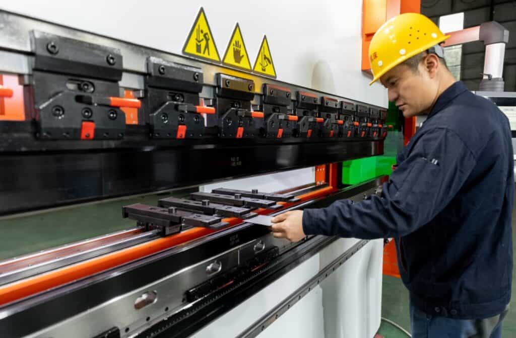
Flange Length Tolerance: Why Does the Backgauge Determine Dimensional Stability?
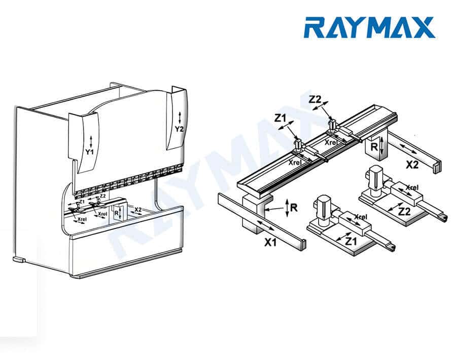
Selecting a Backgauge Based on 4 Key Metrics
|
Parameters |
Function |
Significance of selection |
|---|---|---|
|
X-axis |
Forward/backward positioning |
Determining flange length |
|
R-axis |
Vertical height adjustment |
Suitable for multiple bends and different tooling heights |
|
Z1/Z2 axis |
Left/Right movement |
Suitable for asymmetrical parts and multi-station tools |
|
Backgauge finger rigidity and contact area |
Gauging stability |
Prevents sheet rotation and positioning drift |
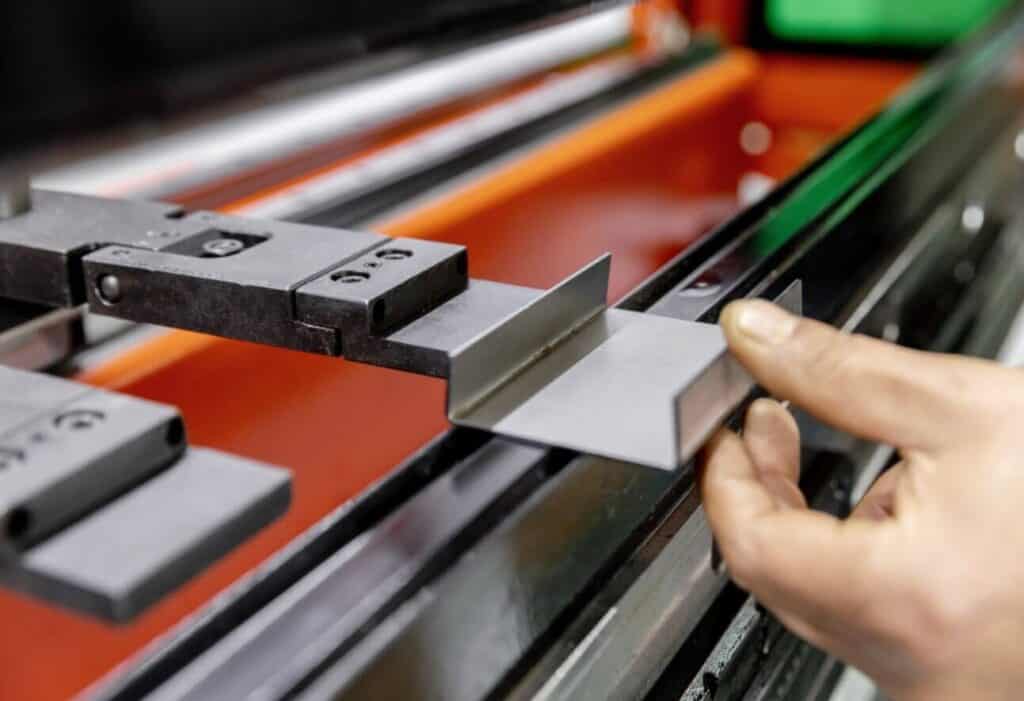
In CNC press brakes, after the press brake back gauge system has been precisely assembled, through calibration and according to standard procedures, it can theoretically achieve very high backgauge repeatability. However, in actual machining, the flange length tolerance still needs to be verified through continuous testing.
.jpg)
On-site Causes of Unstable Flange Length
Unstable flange length usually comes from several sources:
To solve flange length instability at the source, these factors must be checked on site instead of simply adjusting the machine.
When positioning large, thin, or heavy workpieces, the sheet sags under its own weight, causing the actual contact point to shift and resulting in deviations in flange length.
For large panels, electrical cabinet doors, and long, thin workpieces, consider installing a front support or a sheet follower system to prevent the workpiece from sagging under its own weight and drifting away from the backgauge fingers during positioning.
If flange length still drifts after checking the X-axis, gauging method, sheet support, and backgauge fingers, follow this press brake backgauge accuracy troubleshooting process.
What Causes Tight Tolerance Failure? Check Material and Tooling Before Blaming the Machine
Five Major Causes of Tight Tolerance Failure
|
Source |
Typical symptoms |
Correct assessment |
|---|---|---|
|
Fluctuations in material thickness between batches |
Inconsistent angles within the same program |
First, measure the actual thickness of the material |
|
Variations in material strength between batches |
Inconsistent material springback within the same program |
Check the material batch certificates and compare strength variations between different batches |
|
Incorrect V-die opening selection |
Inconsistent angles; inside bend radius does not match the drawing |
Select a V-die opening based on the material and sheet thickness |
|
Tooling wear |
Gradual angle drift after batch production |
Inspect the condition of the punch tip and the shoulder on both sides of the lower die V-groove |
|
Inconsistent measurement methods |
Different measurement results for the same part when measured by different operators |
Secure the measuring tools and measurement points |
When troubleshooting tight tolerance issues, it is essential to first inspect the material, tooling, and measurement conditions before adjusting the machine based on the actual situation.
On-site Troubleshooting Sequence
Do Not Rely on Repeated Machine Adjustments to Meet Tight Tolerances
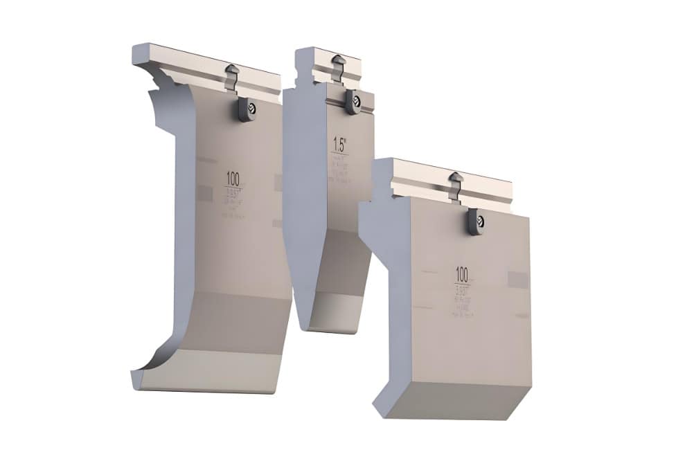
The Tooling Specifications Determine Bending Radius, Tonnage, and Stability
Selection Logic for V-die Opening
When the V-die opening is too small, the required press brake tonnage increases significantly, thereby raising the risk of indentations, cracking, and tooling damage. If the press depth is increased further to achieve a smaller inside radius or a tighter bend angle, the actual contact condition between the workpiece and the lower die will gradually approach bottoming or even coining conditions. At this point, the original air bending tonnage estimate can no longer be used.
The larger the V-die opening size, the lower the tonnage required by the press brake, and the larger the inside bend radius will be; however, the minimum flange length will also increase accordingly. If the flange length specified in the drawing is very short, the V-die opening should not be enlarged solely to reduce tonnage; it is also necessary to ensure that the minimum flange edge can be stably supported on the open edges of the lower die.
When selecting a press brake for small flange parts, we must comprehensively consider factors such as V-die opening rule, tonnage requirements, inside radius size, and material support space.
.jpg)
What Factors Determine Tooling Precision
The tooling directly influences the actual inside bend radius, which in turn affects the unfolded dimensions, springback, and flange length.
For long workpieces, tooling straightness and segmental assembly precision directly affect angle consistency along the entire length.
For appearance-critical parts, the tooling surface condition and indentation control directly determine whether the bent part meets specifications.
Tooling Strategies for Different Part Types
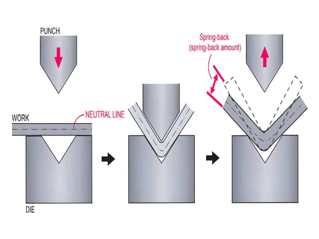
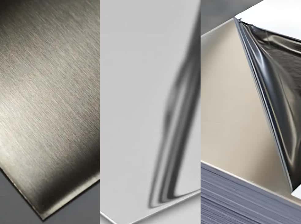
Material Springback Determines Angle Compensation: Different Materials Cannot Use the Same Parameters
The Impact of Material on Tolerances
|
Materials |
Springback characteristics |
Key considerations for selection |
|---|---|---|
|
Mild steel/Cold-rolled steel |
Stable and predictable |
Suitable as a standard test material for machine accuracy acceptance testing |
|
304 stainless steel |
Significantly greater springback than carbon steel |
Requires stronger angle compensation, stable tooling, and appropriate V-die openings |
|
316 stainless steel |
Like 304, requires strict control of springback, surface indentations, and batch-to-batch variations |
Requires attention to tonnage allowance and trial bend records |
|
Aluminum sheet |
Soft but prone to surface damage; moderate springback |
Pay attention to die indentations and surface protection |
|
High-strength steel |
High springback; high risk of cracking |
Must use large V-die openings, large inside bend radii, and sufficient tonnage allowance |
The table above serves as a typical reference for selection. The default conditions are standard sheet thicknesses of 1–4 mm, V≈8T, air bending, 90° bends, and tooling in good condition.
For different sheet thicknesses, V-die openings, and process conditions, the actual springback must be determined based on trial bend records.
Material Batch Variations Must Be Considered in Selection Discussions
Even for the same material grade, different batches may exhibit variations in thickness and strength, leading to inconsistent bending results under the same bending program. The tighter the drawing tolerances, the more critical it is to account for these batch variations.
Achieving truly stable batch production relies on recorded material parameters, program compensation, and acceptance records—not on operators adjusting the machine based on intuition each time.
.jpg)
How CNC Control Helps Manage Tolerance Errors
Core Capabilities to Look for in a Control System
The true value of a control system lies in its ability to reliably manage the Y-axis, backgauge, crowning, material springback compensation, and program repeatability.
When Are Angle Measurement or Automatic Angle Compensation Required?
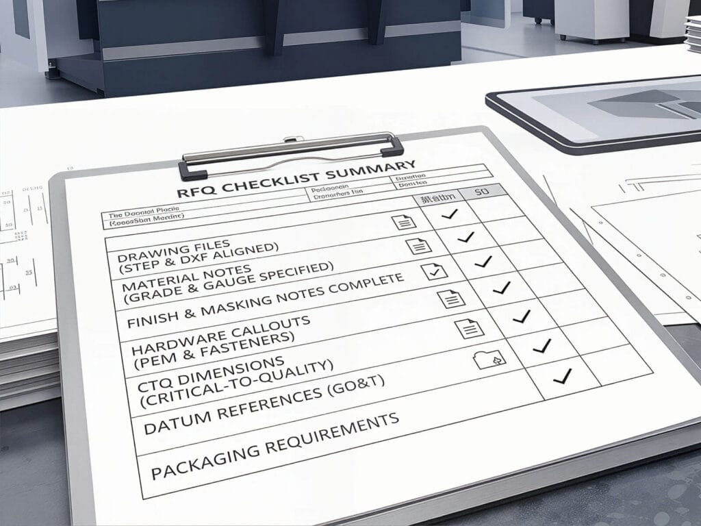
Checklist—Tolerance Information to Provide to the Supplier Before Purchasing a Machine
Information the Customer Must Provide
Before purchasing, we must clarify the following issues and provide them to the supplier:
Only by reviewing your complete workpiece information can the supplier determine which machine and configuration are best suited for you.
Press Brake Tolerance Specification Sheet
|
Information |
Specifications |
|---|---|
|
Material |
|
|
Thickness |
|
|
Bend length |
|
|
Target angle |
|
|
Angle tolerance |
|
|
Flange length tolerance |
|
|
Inside radius |
|
|
Minimum flange |
|
|
Surface requirement |
|
|
Batch size |
|
|
Number of bends per part |
|
|
Current rejection problem |
|
|
Required production speed |
|
|
Drawing or sample |
Please fill out this form and send it to Raymax. Our engineers will recommend the proper machine configuration based on your actual operating conditions and tolerance requirements.
Acceptance Testing—Don’t Just Look at the First Part; Check for Stability in Continuous Production
8 Steps for Acceptance Testing
This acceptance test procedure prevents situations where the first part passes but the batch is scrapped. Before accepting the machine, use this press brake bending accuracy checklist to verify angle, flange length, straightness, repeatability, and batch stability.
Clarifying Test Conditions for Specification Values
Measurement data obtained under no-load conditions cannot be directly equated with actual bending results. Therefore, contract acceptance clauses must explicitly state specific measurement conditions, rather than simply listing an accuracy figure.
Acceptance Record Form
|
Test items |
Measurement methods |
Acceptance criteria |
|---|---|---|
|
Center angle |
Measure the center position using a digital angle gauge |
Based on drawing tolerances |
|
Left, center, and right angles |
Three-point measurement for long workpieces |
Check the maximum angle deviation |
|
Flange length |
Measure using a caliper |
Based on drawing tolerances |
|
Straightness |
Measure by placing a straightedge and feeler gauge flush against the bend surface |
Calculate the allowable value based on the bend length |
|
X-Axis repeatability |
Implement backgauge positioning at the same coordinate and perform multiple positioning tests using a dial indicator |
Check for repeatability deviation |
|
Batch stability |
Measure 5–10 pieces consecutively |
Check the range of variation, not just the average |
The key metric for acceptance evaluation should be the range, not the average. True production capability is demonstrated in continuous processing, where both the maximum and minimum values fall within tolerance.
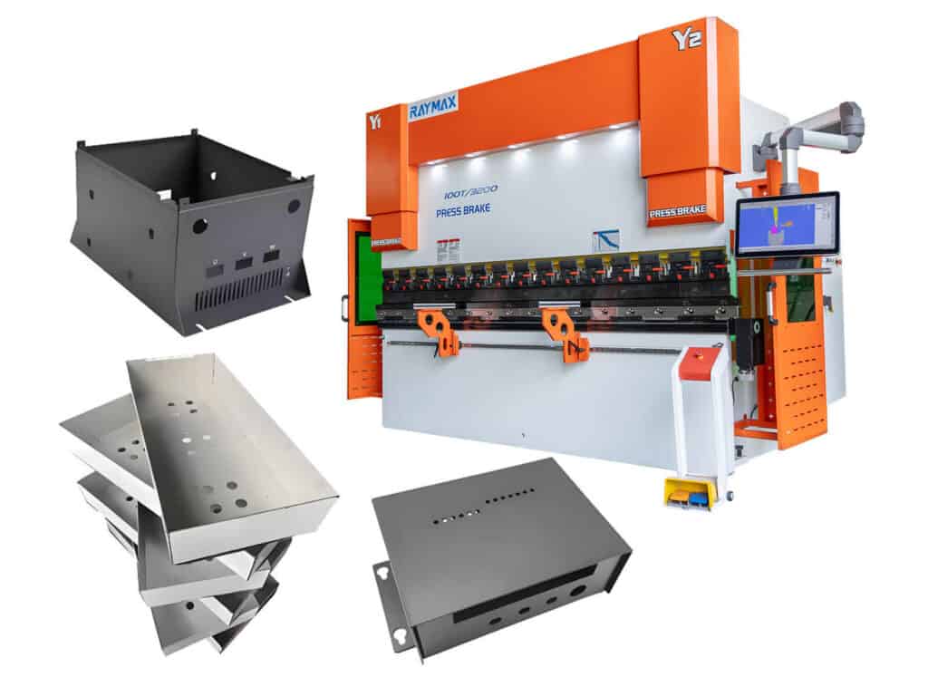
How should a press brake be configured for different types of parts?
|
Part type |
Major tolerance risks |
Key features of recommended configurations |
|---|---|---|
|
Electrical cabinets/Enclosures |
Flange dimensions, door gap, assembly hole positions |
CNC backgauge, crowning system, precision tooling |
|
Stainless steel exterior components |
Springback, indentations, angle drift |
Springback compensation, non-marking tooling, stable V-die opening |
|
Long door panels/Uprights |
Angle inconsistency: left, center, right |
High-rigidity frame, CNC crowning |
|
Thick-plate structural components |
Insufficient tonnage, cracking, tooling damage |
High tonnage, wide V-die opening |
|
Multi-bent parts |
Cumulative errors, difficulty in material alignment |
Multi-axis backgauge, offline programming, process simulation |
|
Small-batch repair parts |
Frequent changeovers, low efficiency |
User-friendly CNC interface, quick-clamping system, universal tooling library |
|
High-strength steel parts |
Significant springback, high risk of cracking |
Wide V-die opening, large inside bend radius, rigorous trial bend |
Different parts present different tolerance risks. For electrical cabinet components, consider flange length and the consistency of long parts; for stainless steel, consider springback and surface finish; for thick plates, consider press tonnage and structural rigidity.
Before selecting a machine, you must first identify the part type and primary tolerance risks, and then determine the tonnage, backgauge, crowning, tooling, and control system configuration.
Conclusion
When selecting a press brake, we must choose based on tolerance requirements rather than focusing solely on whether the tonnage is sufficient. Tonnage, working length, and the press brake control system form the foundation, but truly reliable press brake specifications must encompass the machine, tooling, materials, process, and acceptance criteria.
If you are evaluating whether a press brake can meet your drawing tolerance requirements, send Raymax your material, sheet thickness, bending length, target angle, angle tolerance, flange length tolerance, target inside bend radius, minimum flange length, surface finish requirements, and batch size requirements to get a press brake recommendation based on your actual production conditions.
Ready To Upgrade Your Metal Fabrication Line?
Email Us For A Free Consultation.
Frequently Asked Questions (FAQs)
Related Blog
-1024x768.jpg)
10 Common Press Brake Air Bending Problems: Causes, Troubleshooting, and Fixes
a guide to 11 Types of press brake bending process
Air Bending vs Bottom Bending vs Coining: Which Press Brake Bending Method Is Right for You?
CNC press brake axis: Mastering Configurations from 2-Axis to 8+1 for Pro Results
Definition of press brake tool material
Electrical Enclosure Bending: Flat Pattern, Flange Accuracy & Fit-Up Issues
How to Improve Press Brake Bending Consistency: Causes, Checks & Solutions
How to Measure Press Brake Bending Angle: Tools, Methods & Calibration Pitfalls
How to Reduce Springback in Press Brake Bending (SS/AL/MS Checklist)
How to Use a Press Brake Machine for Precise Bending
Hydraulic Press Brake Troubleshooting: The Ultimate Guide to Fix Common Problems
Non-Marking Press Brake Bending: How to Prevent Scratches on Brushed, Mirror-Finish & Film-Protected Sheets
Post Your Review
Share Your Thoughts And Feelings With Others