
Francis Pan
Francis Pan is the Foreign Trade Manager of RAYMAX, with over 10 years of experience in sheet metal fabrication equipment and CNC machinery. He has worked closely with manufacturers worldwide on press brakes, fiber laser cutting machines, fiber laser welding machines, and practical production-oriented metal processing solutions.
Top Guidelines
-1024x768.jpg)
-1024x768.jpg)
-1024x768.jpg)
-1024x768.jpg)
Table Of Contents
Stay in the the loop
Subscribe To Our Newsletter
Summary
Bend angle measurement is not as simple as placing an angle gauge on the part. Before measuring a bend angle, we must first confirm which angle is being measured and whether the measurement is taken after bending is completed or in real time during the bending process. In many workshops, angles keep drifting out of tolerance because the wrong angle was measured, the wrong location was checked, or the measurement was taken at the wrong time.
A standard measurement process should follow this sequence:
confirm the process conditions → do the first-piece trial bend → after the workpiece has been released from the tooling and springback has occurred → measure the left, center, and right points along the full length of the workpiece → record the actual measured angle and the deviation from the target angle → the final decision is whether to adjust the program, adjust the crowning compensation, or check the tooling and force distribution.
This article focuses on bend angle measurement tools, standard measuring actions, the measurement process, and common problems to make this logic clear.
30-Second Checklist: How to Measure Bend Angles in Different Scenarios
|
Scenarios |
Recommended methods |
Core reasons |
|---|---|---|
|
Quick confirmation of the first piece |
Digital angle gauge |
Fast readings for first-piece verification and program fine-tuning |
|
Ordinary batch sampling inspection |
Digital angle gauge + fixed measuring points |
Stable sampling action can be established to reduce human error in reading. |
|
Consistency check for long workpieces |
Left, center and right point measurement |
Single-point measurement cannot represent the entire length, but must be combined with the distribution of angular differences in the three-point measurement. |
|
High-springback materials |
Online laser angle measurement system |
Real-time recognition of springback variations, eliminating the need for repeated trial bends. |
|
High-precision mass-produced parts |
Online laser angle measurement system + CNC control system |
Real-time measurement and closed-loop correction can reduce angle deviation. |
|
Fixed-angle batch parts |
Dedicated angle templates / inspection fixtures |
Fast inspection with fewer manual reading errors |
|
Machine/program calibration |
Standard specimen + fixed material + fixed tooling + fixed measuring method |
Calibration results cannot be reused if conditions are not uniform. |
Let’s start by clarifying the most critical point: Which angle are you actually measuring?
Final inspection examines the actual included angle of the finished workpiece, not the “degree of bend” mentioned by the operator
Drawing acceptance and subsequent assembly are based on the actual included angle of the formed workpiece. On the shop floor, the shop-floor phrase “bend to 90°” may have different meanings in different contexts, which may refer to the angle entered in the program, the angle marked on the drawings, or the finished workpiece angle. When angle measurement is part of a formal FAT/SAT angle accuracy test, the record should clearly state the target angle, actual measured angle, measurement position, measuring tool, and pass/fail result.
Therefore, the angle language should be unified from the beginning, otherwise the subsequent correction will be more and more confusing.
Included angle and complementary angle must be unified first
For example, if the drawing requires a 135° bend angle, that 135° is the included angle. Since 180° − 135° = 45°, the 45° angle is the complementary angle. Many control systems have different default logic for angles, so operators should pay attention to the angle definition in the system interface before operation. The whole shop must use a unified angle definition for both measurement and correction.
For clarity, this article uniformly refers to the true internal angle between the two sides of the finished part as the “included angle”; the angle obtained by subtracting the included angle from 180° is referred to as the “complementary angle.”
.jpg)
Measuring the wrong angle is not a small error—the correction direction can be completely reversed
If the definition of the angle is confused, it is easy to measure the wrong angle, which may cause the program to correct the direction opposite to the actual direction of correction.
For example, when you are doing angle correction, you mistakenly see the included angle as complementary angle, thinking that you are compensating for the reduced angle, but in fact the program will only compensate in the opposite direction, causing the angle to become larger instead of smaller.
The reasons for this error usually lie in the lack of skill of the new operator, unclear communication during the handover, and the different ways of defining angles in different control systems.
4 Common Bend Angle Measurement Tools: When to Use Each One
Mechanical protractor: can be used, but do not treat it as a precision control tool
A mechanical protractor is suitable for rough inspection, teaching and low precision requirements of workpieces. Its biggest problem is not measuring inaccuracies, but its readings are easily affected by human action, if there is parallax, poor contact, or interference from local deformation, the results may be biased.
Therefore, it can only roughly determine the angle accuracy, and is not suitable for first-piece approval for high-consistency orders.
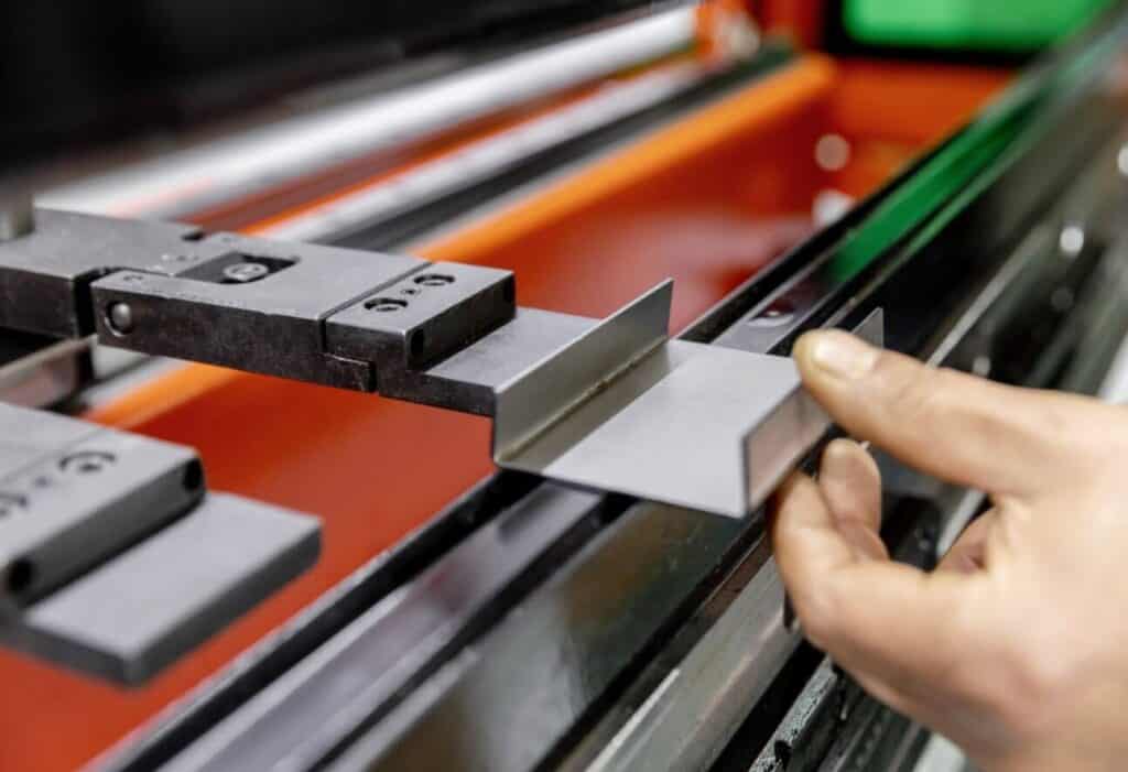
Digital angle gauge: the workhorse for first-piece approval and batch sampling inspection
This is the main measuring tool in the workshop. Its advantages are fast readings, a more intuitive digital display, and a low operating threshold, especially suitable for first piece confirmation and batch sampling. However, it is still an offline manual measurement, which only displays the result and cannot feed the result back to the CNC system for automatic correction. When measuring short-edge parts, uneven surface parts, and non-magnetic material parts, the measurement results are easily affected by the unstable base.
Therefore, do not think that the digital angle gauge is necessarily accurate, the actual accuracy will still be affected by the material and operation mode.
Dedicated angle inspection fixture / angle template: an efficient solution for high-frequency fixed-angle parts
If the workshop is producing standard bending parts of 90° and 135° repeatedly over a long period of time, the use of a special angle template is much faster than repeated readings because it does not require re-measurement of each piece. Its value lies in its ability to minimize human reading errors and effectively shorten judgment time, making it particularly suitable for highly repetitive, single-angle batch scenarios that require quick inspection.
It cannot replace all measuring tools. It is specifically used to quickly determine whether fixed-angle batch parts are qualified, making the inspection process simpler and more consistent.
Online laser angle measurement system: truly transforming “measurement” into “control”
An online laser angle measurement system can read the actual formed angle in real time through laser triangulation or 2D/3D contour sensing and feed the measurement data back to the control system. Its value lies in its ability to cope with variables such as material thickness fluctuations, hardness differences, grain direction differences and springback, making it ideal for high-precision batch parts, high-springback materials, and orders with high first-piece scrap costs.
.jpg)
How to Measure Bend Angles Correctly
Establish the reference surface before reading the angle
The gauge must contact a true straight section of the workpiece. It must not be placed on the transition radius near the bend line, and burrs, dents, or locally warped edges must not be used as reference surfaces. Once the gauge is not seated properly, the reading is meaningless.
The timing of the measurement must be consistent: the angle under pressure and the angle after pressure release are not the same
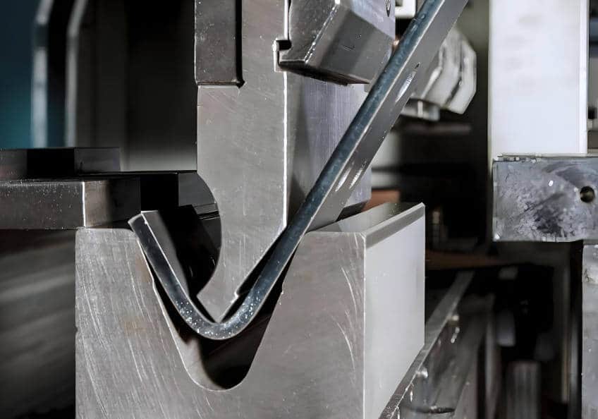
When the ram is still under pressure and the workpiece has not completely left the lower die, the angle at that moment cannot be taken as the final product angle. This is because in air bending, after the pressure is released, the material will springback, resulting in a change in the final angle.
Therefore, we must measure the angle after the workpiece has completely left the lower die, the internal stresses in the material are released, and the springback is complete.
When measuring long workpieces, don’t just measure the middle—the three-point measurement method is crucial
For long workpieces, we must measure at the left, center and right points of the workpiece. Because when the press brake is under force, the table and ram may produce elastic deformation, which can easily lead to angle deviation between the center and the ends of long workpieces.
The direction of this deviation is usually affected by machine deflection, the state of crowning compensation, tooling clamping and force distribution, and it may not always be the case that the middle angle is greater. Therefore, we cannot take the angle of one point to represent the angle of the full length of the workpiece.
After measuring the left, center, and right points, you can diagnose crowning from left-center-right angle data to decide whether the issue is insufficient crowning, excessive crowning, or ram parallelism.
Measuring direction and action must be fixed, don’t measure this way today and that way tomorrow
For the same team, the same type of workpiece, and the same machine, the measuring tool, measuring position, and measuring direction must be consistent. You cannot measure the left side today and the right side tomorrow, or measure the center today and the end tomorrow.
The workshop’s greatest fear is not the lack of precision measuring tools, but everyone is using their own action to measure the same angle. After the angle measurement is completed, you can use the “press brake bending accuracy checklist” to determine whether the accuracy problem has been resolved.
.jpg)
Standard measurement process: how to measure correctly on the shop floor (On-site SOP version)
Confirm the material, sheet thickness, V-die opening and target angle first
If the process is not taken into account, the angle reading has no meaning. Because the final angle will be affected by material strength, sheet thickness, V-die opening, the target inside radius, and the bending method, the angle is not an independent variable, but the result of the combined action of different process parameters.
Perform a standard test bend before calibration
The first-piece trial bend is the benchmark for all subsequent measurements and parameter corrections. If the tooling is not centered, the workpiece is not positioned correctly, or the workpiece is placed incorrectly during the first trial bend, the measurement data will be meaningless.
Therefore, it is necessary to ensure that clamping, centering, positioning, and workpiece handling on the first piece are all correct, before starting to measure the angle and correction. If the first-piece setup is not yet repeatable, review the basic workflow of using a press brake for precise bending before using the measured angle for calibration.
Unified tools, unified measurement points, unified recording methods
During the calibration process for the same batch of parts, different brands and different types of measuring tools must not be mixed, and you must not read the angle as the included angle today and as the complementary angle tomorrow. There must be one standardized measurement system; only then will the measured data be meaningful.
Record “target angle – measured angle – deviation – correction”
Unrecorded data cannot be reused.
Records include at least: material, sheet thickness, V-die opening, tooling angle, target angle, measured angle of the first piece, the difference between the left, center and right angles, the amount of correction entered into the program, whether or not to enable the crowning compensation, as well as the final stable angle of the finished product.
Only if this is recorded can it be reused in the next production run.
Why Bend Angles Are Still Incorrect After Measurement
Mistaking the tooling angle for the final angle of the workpiece
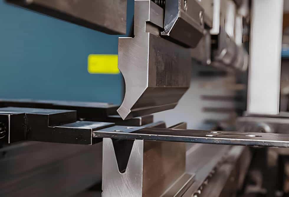
The angle of the tooling and the angle of the finished workpiece are not the same concept, especially in the air bending process, the angle of the workpieces is determined by the ram depth, not the same as the angle of the tooling. If the tooling angle is directly understood as the finished workpiece angle, then the subsequent measurement, correction and crowning compensation may be problematic.
.jpg)
Measuring only one point, taking local data as the conclusion of the whole piece
When measuring long workpieces, a single point measurement is not enough, because once the force distribution along a long workpiece changes, the bend angle may no longer remain consistent across the full length. If you measure only one point and then change the overall program parameters, the result will only become more chaotic.
Therefore, when measuring, we should first determine whether the overall angle offset, or the full-length angle distribution is uneven.
Ignoring springback and treating the process angle as the final angle
In many cases, the issue is not machine accuracy at all, but the failure to account for material springback. When bending high-strength steel, stainless steel, and thin-sheet parts, springback in these materials will be more obvious. If the angle during the bending process is taken as the basis for adjustment, it is easy to cause the program correction direction to be wrong. Therefore, knowing how to reduce springback in press brake bending is an essential professional skill that must be mastered before bending sheet metal in a factory.
.jpg)
The workpiece is not placed firmly, the gauge is not seated properly
This is a basic but very common error. A workpiece placed diagonally, or a gauge resting on a burr edge or a local deformation zone, is being measured incorrectly, once these measurement actions are not correct, the measured data will deviate from the actual angle.
Mistaking material variation for machine drift
Different batches may have small differences in material thickness and rolling grain direction, resulting in springback changes. Therefore, we cannot apply the correction parameters of the previous batch of material directly to the next batch of material, and we need to re-calibrate and re-test after each batch of material replacement.
True Calibration Is Not Just Getting the Angle Right After a Few Trial Bends
Calibrate the measurement system first, then the machine
If the measurement tool is not unified, the measurement method is not unified, the measurement position is not fixed, then the subsequent calibration of the machine based on the measurement data will be based on unreliable data, and no matter how to adjust the accuracy can not be guaranteed.
Therefore, before calibrating the machine, make sure that the measurement actions are uniform.
Calibration must be checked at four levels: gauge, program, backgauge, machine force distribution
Calibration must use the standard test piece, do not use random production parts as calibration test pieces
If there are some order pieces with holes, short edges, relief cutouts or local interference features, these features will change the local force distribution, so it is not suitable for basic calibration of machine tools. It is better to use the standard test piece with uniform material, thickness and length to do the basic calibration, and remove all the irrelevant variables, in order to have an accurate judgment on the accuracy of the machine tool.
For an overall angle deviation, check angle correction first; if the center and both ends are inconsistent, check crowning and force distribution
If the angles of the left, center and right points of the workpieces are generally the same, but the overall deviation is either too large or too small, you should first do angle correction / depth correction in the control system, and then correct the ram depth or Y-axis parameters according to the system logic.
If the angle differs between the center and the two ends of the workpiece, it should not be treated as an overall angle deviation. You should first check whether the crowning compensation is sufficient, whether the tooling joints are stable, whether clamping is secure, and whether force distribution across the table is uniform. Eliminate these factors before considering other adjustment measures.
What is the first thing to check when there is an inconsistency between the left and right angles, or between the two ends?
When analyzing the problem of angle deviation of long workpieces, it is necessary to distinguish the deviation pattern first: whether the entire bend line shows the same angle deviation, whether the center differs from both ends, or whether the left and right sides are asymmetrical.
Wrong judgment of the type of deviation may lead to the wrong direction of subsequent adjustment, thus affecting the final accuracy.
Look at the deviation pattern first, don’t change the program right away
When dealing with long workpieces angle problems, the first step is not to change the program immediately, but to judge the deviation pattern first.
If you modify the program, adjust the compensation value or adjust the tooling directly without distinguishing the deviation pattern, the adjustment direction will only move further off target. Only by determining the deviation pattern first and then doing troubleshooting, can the problem be solved more efficiently.
Re-check crowning, tooling clamping and V-die opening matching
Angle inconsistency does not necessarily mean the tonnage is insufficient. In many cases, it is caused by incorrect compensation settings, poor tooling condition, or improper V-die opening selection.
Therefore, when the angle is wrong, you should first check the crowning compensation, tooling clamping, and V-die opening, rather than suspecting insufficient tonnage.
Checking program entry and correction direction last
Program modification parameters should be placed in the last step. This is because if the machine force distribution and tooling are not the same, and the measurement process is wrong, then repeated program changes will only make the results more chaotic.
The correct sequence should be: first check the machine condition and force distribution, then check the measurement action, and finally change the program parameters.
When to Use an Online Laser Angle Measurement System Instead of a Manual Angle Gauge
When angle tolerance is tight
When the goal of bending is not just to be able to bend, but to have a high degree of angular consistency, the limitations of manual measurement are clearly exposed. In this case, the value of an online real-time closed-loop angle measurement system is significantly greater.
When the material fluctuates greatly and springback is obvious
For stainless steel, high-strength steel, multiple batches of materials, frequent changeovers of materials, an online laser angle measurement system becomes more valuable. Because the springback of these materials is more obvious, it is difficult to keep up with the manual sampling alone.
The online laser angle measurement system can measure the angle in real time when bending, and feedback the measurement results to the CNC control system for angle correction, thus forming a closed-loop control, which can effectively reduce repeated trial bends and batch deviation. This shifts control from reactive correction to real-time control, avoiding subsequent batch rework.
When first-piece scrap costs are high and rework is costly
The higher the cost of first-part trial-and-error and the more expensive the rework, the less likely it is that multiple attempts will be made purely on the basis of experience.
The value of online laser angle measurement system is to quickly find and correct the angle deviation in the bending process, so that the first-piece pass rate is higher, and can significantly reduce the number of trial bends, avoiding rework and cost waste due to lack of human experience, parameter adjustment errors.
Multi-shift, high consistency batch parts
In a multi-shift scenario, different measurement habits of operators in different shifts can lead to drift in the angle of the same batch of orders. The value of the online laser angle measurement system is that it can eliminate the differences in manual operation and ensure that different shifts can maintain the same angle when making the same batch of orders.
When selecting equipment, this item is more worthy of confirmation than the nameplate tonnage
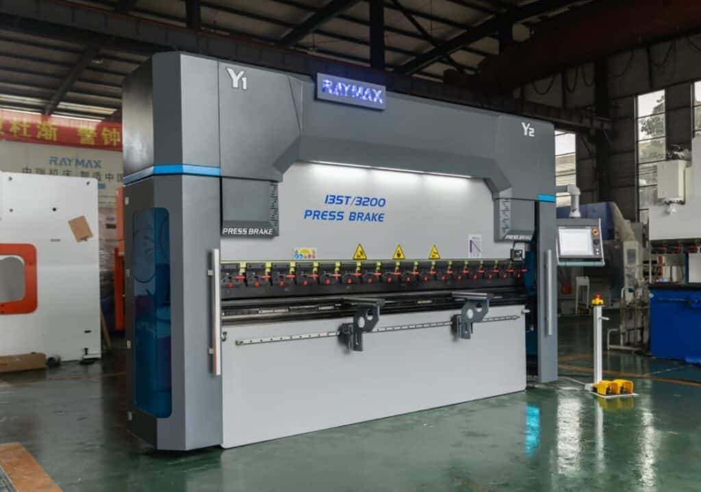
When purchasing a press brake, it is not enough to look only at the machine’s tonnage and bending length. It is more important to confirm whether the machine supports online angle measurement, whether angle correction and crowning compensation can work together, and whether backgauge repeatability is stable ( If so, backgauge accuracy troubleshooting is required).
This is the key ability to determine whether the press brake can be stabilized for batch production after first-piece verification.
.jpg)
8 Common Bend Angle Calibration Pitfalls on the Shop Floor
Mixing included angle with complementary angle
Mistaking tooling angles for finished workpiece angles
Measuring only one measuring point
Failure to distinguish between the angle under pressure and the angle after pressure release
Reading directly without calibrating the gauge
Using the previous batch’s correction after changing material
Blindly change the program without checking crowning and tooling status
Taking “tested and working” as “calibrated”
Conclusion
The real difficulty in bending angle control lies not in measurement, but in the ability to form a closed loop of measurement, deviation judgment, program correction, and machine capability. It is not difficult to adjust one piece correctly through operator experience alone; the key is whether the result of the first piece can be stably repeated across the whole batch.
When purchasing a press brake, if you only compare tonnage and length, you will definitely lose out on first-piece pass rate and batch consistency later. What you really need to confirm is: how the control system corrects the angle, whether it supports online angle measurement, whether crowning matches the machine’s deformation characteristics, whether backgauge repeatability is stable, and whether tooling clamping is stable.
If you are considering purchasing a press brake that can accurately control the bending angle, you can send us your material specifications, sheet thickness and angle tolerance requirements, and Raymax will provide you with reasonable configuration recommendations.
Ready To Upgrade Your Metal Fabrication Line?
Email Us For A Free Consultation.
FAQ
Related Blog
-1024x768.jpg)
10 Common Press Brake Air Bending Problems: Causes, Troubleshooting, and Fixes
.jpg)
Stainless Steel Bending Force: 304 vs 316 (Correction Factors, Springback & V-Die Selection)
The Heart of Every Press Brake: Select, Maintenance & Upgrade Hydraulic Cylinders
-1024x768.jpg)
Press Brake Tonnage Comparison: Air Bending vs Bottoming vs Coining (How Force Changes + Safety Margin)

Press Brake Clamping System Guide:Types,Tooling Compatibility&Faster Tool Changeovers
-1-1024x768.jpg)
How to Spec a Press Brake for Tolerance: Angle, Flange Length, Crowning, Backgauge & Acceptance Checklist
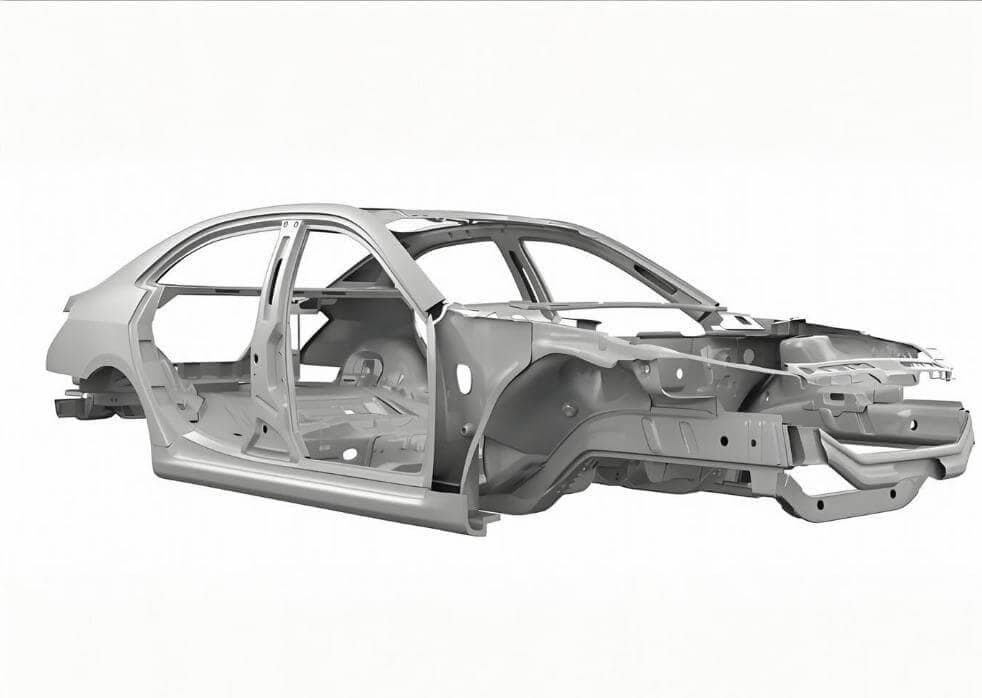
Press Brake for Automotive Sheet Metal Parts: Springback Control, Mark-Free Tooling & Hemming
a guide to 11 Types of press brake bending process
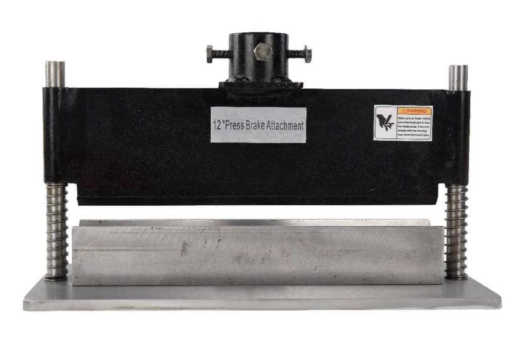
Press Brake Attachment Guide (2026): Types, Uses, Tooling & Quick-Change Systems
Press Brake Bending Basics: Everything You Need to Know for Efficient Bending
What Is a Sheet Metal Press Brake Machine? Working Principles, Bending Techniques & Buying Guide
Press Brake Air Bending: Guide to Principles, Calculations & Best Practices
Post Your Review
Share Your Thoughts And Feelings With Others
One response to “How to Measure Press Brake Bending Angle: Tools, Methods & Calibration Pitfalls”
Gerçekten çok faydalı ve bilgilendirici bir içerik olmuş, emeğinize sağlık.