
Francis Pan
Francis Pan is the Foreign Trade Manager of RAYMAX, with over 10 years of experience in sheet metal fabrication equipment and CNC machinery. He has worked closely with manufacturers worldwide on press brakes, fiber laser cutting machines, fiber laser welding machines, and practical production-oriented metal processing solutions.
Top Guidelines
-1-1024x768.jpg)
-1024x768.jpg)
-1024x768.jpg)
-1024x768.jpg)
Table Of Contents
Stay in the the loop
Subscribe To Our Newsletter
Quick answers
What is crowning compensation on a press brake?
During bending, the crowning compensation system actively applies a counter-curve to the table or ram to offset the deflection caused by high loads on the machine, thereby improving angle consistency at the left, center, and right positions of long workpieces.
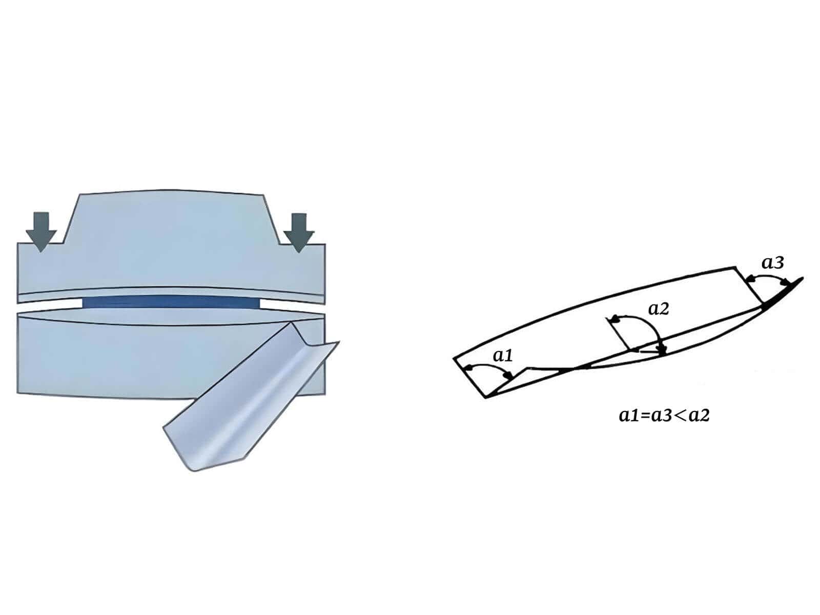
Why is the angle always larger in the middle of long workpieces?
When bending long workpieces, the machine is subjected to significant forces, causing the ram and table to undergo elastic deformation, which results in insufficient penetration depth at the center of the machine. As a result, the angle at the center of the long workpiece becomes larger, while the angles at both ends become smaller.
How to Choose among the three compensation methods?
Generally speaking:
What problems will this article help you solve?
This article will clearly explain the three concepts of deflection, angle variation, and crowning. It will then compare the three compensation systems—hydraulic, mechanical, and CNC-linked—to provide you with a set of methods for on-site troubleshooting and parameter adjustment. After reading this article, you should be able to make a basic judgment about whether your current crowning settings are reasonable and whether the problem truly lies in the crowning system.
On-site challenges: why are angles inconsistent when bending long workpieces?
The four most common issues in the workshop:
Why are long workpieces, thick plates, and high-tonnage applications more prone to issues?
Because long workpieces span a greater bending length, the load span across the machine becomes larger. This results in higher machine loads, causing the ram and table to inevitably undergo “boat-shaped” elastic deformation. The longer and thicker the workpiece, the higher the tonnage typically required, and the greater the likelihood of deformation in the ram and table.
What practical losses does this type of angle variation cause?
Angular variation can lead to difficulties in subsequent assembly, inconsistent gaps during welding or assembly, scrap of cosmetic parts, increased number of test bends, and reduced batch consistency. Both material and labor costs will rise, and delivery delays may also occur.
Clarifying key concepts: fully understanding the interrelationship between deflection, angle variation, and crowning
What is deflection?
Deflection is a physical phenomenon. Generally speaking, as long as the force applied during bending is sufficiently large, the machine structure, ram, table, and load-bearing system will undergo a certain degree of elastic deformation.
What is angle variation?
When a press brake undergoes deflection, the center sags, causing uneven force distribution along the entire length of the bend. This causes angle variation along the bend line of a long workpiece, with the center angle typically opening more than the angles at both ends.
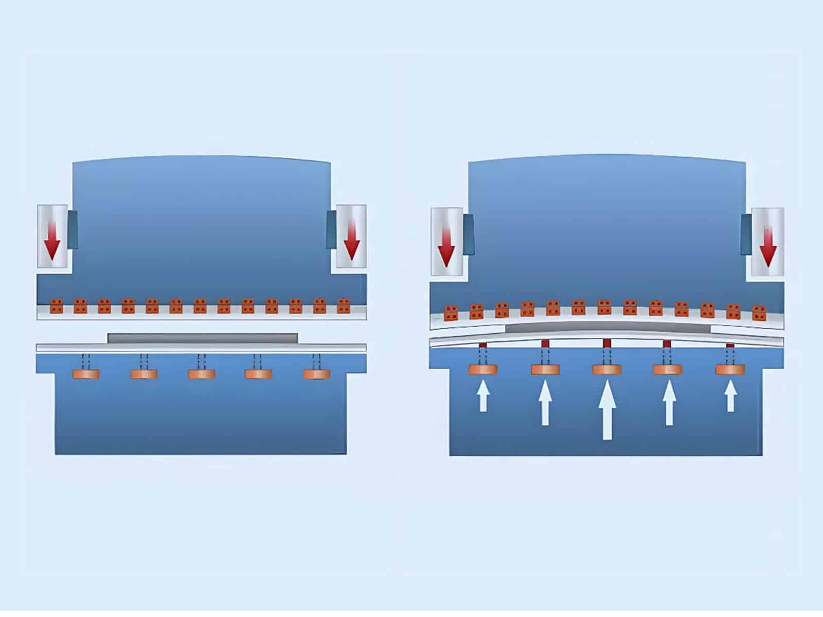
What is crowning compensation?
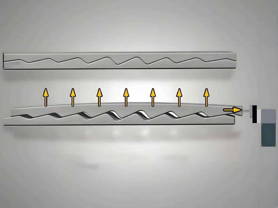
Crowning compensation is a corrective measure. The system proactively creates a compensation curve on the table that opposes the direction of load-induced deformation. When the machine is loaded, this helps keep the tool penetration depth as consistent as possible along the entire length.
Logical relationship among the three
Stress-induced deformation → Angle variation → Deflection compensation
The machine and its load-bearing system undergo deflection under bending loads, which in turn causes angle variations along the length, and these are finally corrected through crowning.
Warning from a Veteran Engineer
Installing a crowning system does not guarantee that the workpiece will never experience angular errors. This is because the actual angle is also influenced by various factors, including material thickness, hardness, rolling direction, Y1/Y2 positioning accuracy, and frame rigidity. While the crowning system is crucial for correcting angle variations, it is never the sole determining factor.
If the center angle still differs from both ends after adjustment, follow this crowning troubleshooting guide to identify whether the cause is insufficient crowning, excessive crowning, tooling, hydraulics, or ram parallelism.
Working principle of crowning in press brakes
Why must the compensation direction be opposite to the direction of deformation under load?
Because the table typically forms a “downward concave” shape when subjected to force, we must create an upward compensation curve during compensation to offset this deformation, thereby ensuring a more consistent penetration depth along the entire bending line.
At what levels does compensation typically occur?
Compensation typically occurs at the following three levels:
What is the true objective of compensation?
Compensation is not intended to completely eliminate deformation, but rather to ensure that the angles of the final bent workpiece are more consistent along the entire bending line, reduce the need for manual test bends, and achieve greater stability during mass production.
Comparison of press brake crowning systems: mechanical, hydraulic, or CNC dynamic—which one should you choose?
Mechanical crowning system
Hydraulic crowning system
CNC dynamic crowning
Head-to-head comparison chart for system selection
|
Comparison criteria |
Mechanical compensation system |
Hydraulic compensation system |
CNC dynamic crowning system |
|---|---|---|---|
|
Compensation principle |
Relative sliding of tapered wedges |
Hydraulic compensation cylinder lifts upward |
CNC intelligent calculation + actuator linkage |
|
Level of automation |
Medium |
High |
Extremely high |
|
Adjustment accuracy |
Very high |
Fairly high |
Extremely high |
|
Repeatability |
Very high |
Good |
Extremely high |
|
Response speed |
Good |
Fast |
Fast |
|
Maintenance complexity |
Low |
Medium |
Medium |
|
Reliance on hydraulic systems |
No |
Yes |
Depends on the type of drive hardware |
|
Significant reduction in trial bends |
No |
No |
Yes / Depends on operating conditions |
|
Applicable sheet thickness and operating conditions |
Thin sheets, high precision, long workpieces |
Medium-to-heavy plates, high tonnage |
Various operating conditions, including multiple product varieties, small batch sizes, frequent changeovers, and high automation |
|
Budget level |
High |
Medium |
Highest |
|
Typical applications for which it is best suited |
Precision stainless steel, cosmetic parts |
Construction machinery, steel structures |
Automation, frequent changeovers |
Press brake crowning troubleshooting: If the angle of a long workpiece is incorrect, check this checklist first
Before changing compensation values blindly, review the full diagnosis path for press brake angle inaccuracy.
Symptom A: The angle in the middle is larger than at both ends (open)
Troubleshooting: When the penetration depth at the center of a long workpiece is insufficient, the angle in the middle will be larger than the angles at both ends. This indicates that the deflection at the center of the machine has not been fully compensated for; in this case, you need to increase the crowning value.
Solution: First, verify that the bend length, sheet thickness, V-die, and material parameters have been entered correctly. If all are correct, appropriately increase the crowning value.
Symptom B: The angle at the center is smaller than at both ends (too tight)
Troubleshooting: When the angle in the middle is smaller than at both ends (over-bend in the middle), this indicates that the system is lifting too high (excessive compensation) or that the measurement reference for the operator’s first-piece test bend was set incorrectly.
Solution: First, verify that the left-center-right bend angle measurement method is consistent, then appropriately reduce the crowning value.
Symptom C: Only the left (or right) side angle is incorrect
Troubleshooting: This is typically not a deflection issue; it may be caused by problems with Y1/Y2 parallelism, cylinder synchronization, tooling wear, tool clamping, or machine installation.
Solution: Use a dial indicator to check the parallelism of Y1/Y2, and inspect the cylinders for internal leakage, the tooling for wear, and verify the correctness of the clamping and machine installation.
Symptom D: Angles change completely when switching to a new batch of material using the same program
Troubleshooting: This is usually a material batch issue. The thickness, hardness, and rolling direction of each material batch may vary, and these variations will affect the actual bending angle.
Solution: Re-measure the material thickness with a vernier caliper, then enter the measured data into the CNC system to have it recalculate the crowning values.
Symptom E: Adjusted compensation, but results remain unstable
Troubleshooting: This may be due to severe tooling wear, incorrect V-die selection, or inconsistent loading procedures by the operator.
Solution: At this point, we should not blindly adjust compensation parameters. Instead, first inspect tooling wear, tooling matching, and clamping conditions. Replace the tooling with a fresh set if necessary and perform a test bend. Only after confirming that the tooling and operating procedures are correct should you adjust the compensation parameters.
Crowning adjustment: how should it be properly calibrated?
Verify before making changes
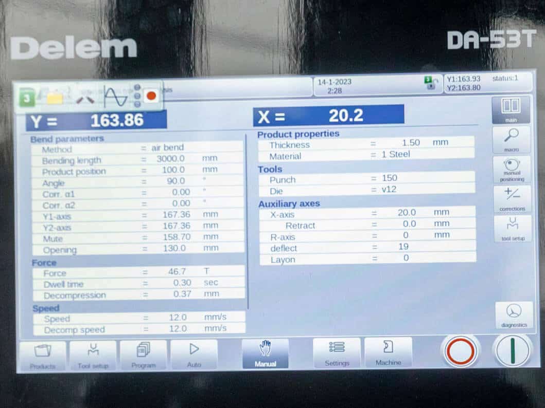
Don’t rush to adjust the compensation parameters. First, check whether the sheet thickness, bend length, material type, and V-die opening displayed on the CNC screen match the actual workpiece on the machine. If even one input is incorrect, the crowning value calculated by the system will most likely be wrong.
When should compensation typically be increased?
Generally, if the angle at the center of the workpiece is larger (greater than at the ends), it indicates that the current crowning value is too low, and compensation should be increased. However, be sure to first rule out issues such as tooling wear, incorrect measurement methods, and programming errors before increasing compensation.
Under what circumstances should compensation typically be reduced?
Generally, when the angle at the center of the workpiece is tighter (smaller than at the ends), it indicates that the current crowning value is too high; or when an old program designed for thick plates is directly applied to a new thin-plate operation, compensation should be reduced in both cases. However, reducing compensation must also be based on actual on-site conditions.
What are the differences in approach between manual compensation and CNC automatic compensation?
Manual compensation relies more on the operator’s experience and trial bending, while CNC automatic compensation relies more on databases, the accuracy of parameter input, and program control. However, automatic compensation is not a cure-all; even with a high degree of automation, we cannot make judgments without considering actual operating conditions.
Additionally, different bending methods (such as air bending and bottoming) may have varying angle sensitivities and compensation adjustment ranges, so the same empirical values cannot be applied universally during on-site assessments.
Why is the angle still unstable even after adjusting the compensation?
This is because angle stability is not determined solely by compensation. Tooling wear, material springback and variations in sheet thickness, Y1/Y2 parallelism, inconsistent feeding operations, inconsistent measurement methods, and issues with the machine’s installation status can all lead to angle instability.
What practical benefits does a high-quality compensation system offer to a factory?
The most direct benefits for long workpieces
The V-die opening size directly determines the actual size of the inside radius (R), thereby affecting the BA, BD, and K values. If the selection of V-die opening is incorrect, it may lead to deviation in the calculation results.
So, it is recommended to bind and manage the unfolding rules with “material, thickness, V-die opening size, bending method”.
Practical value for different types of factories
Why is crowning becoming increasingly important in modern CNC press brakes?
This is because modern sheet metal shops are processing more complex materials, facing ever-higher precision requirements, and switching between orders at a faster pace. For many high-precision orders, relying solely on the experience and intuition of skilled operators is no longer sufficient. Instead, modern CNC press brakes require an integrated compensation system that truly combines compensation, measurement, control, and process parameters to effectively improve product precision.
A guide to avoiding pitfalls: how to choose the right press brake crowning system for your factory?
Six critical questions for factory purchasing managers
Before purchasing a press brake machine, don’t ask the manufacturer, “Does the machine come with compensation?” Instead, ask yourself these six questions:
Different application scenarios require different selection criteria
Key configurations to verify during procurement
When procuring equipment, we must verify: the type of crowning, the adjustment method, whether CNC linkage is supported, the maximum compensation range, resolution or adjustment accuracy, and the compatibility between the press brake, tooling, and control system. No matter how advanced the compensation system is, if the die system is incompatible with the press brake’s clamping, parallelism, and machining capabilities, the final angle consistency will still be compromised.
Most common procurement pitfalls
Conclusion
Deflection is an inevitable physical phenomenon, and crowning is an effective means of addressing this deformation. However, truly efficient bending is never achieved by a single component alone; it relies on the perfect synergy of machine rigidity, a high-precision compensation system, and proper troubleshooting methods.
If you are still struggling with inconsistent bending angles on long workpieces, or if you are unsure which compensation configuration to choose for your facility, please feel free to send your workpiece drawings, commonly used materials, sheet thickness range, maximum bending length, V-die requirements, and target accuracy to our engineering team. Raymax will provide you with the press brake configuration and compensation solution best suited to your needs
Ready To Upgrade Your Metal Fabrication Line?
Email Us For A Free Consultation.
Frequently Asked Questions (FAQs)
Related Blog
Press Brake RFQ Checklist: 14 Fields You Must Provide for an Accurate Quote
How to Spec a Press Brake for Tolerance: Angle, Flange Length, Crowning, Backgauge & Acceptance Checklist
Press Brake Crowning Troubleshooting: Fix Uneven Bend Angles Across Long Parts
How to Improve Press Brake Bending Consistency: Causes, Checks & Solutions
How to Measure Press Brake Bending Angle: Tools, Methods & Calibration Pitfalls
-1024x768.jpg)
Press Brake Backgauge Accuracy Troubleshooting: How to Diagnose Flange Length Errors
.jpg)
Why Is My Press Brake Angle Inaccurate? Common Causes, Diagnosis Flowchart & Fix Priority
Non-Marking Press Brake Bending: How to Prevent Scratches on Brushed, Mirror-Finish & Film-Protected Sheets
Electrical Enclosure Bending: Flat Pattern, Flange Accuracy & Fit-Up Issues
Press Brake Bending Accuracy Checklist: 10 Quantified Factors to Inspect
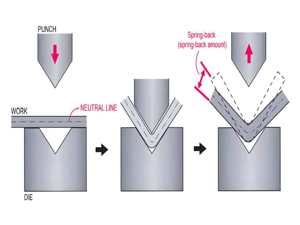
How to Reduce Springback in Press Brake Bending (SS/AL/MS Checklist)
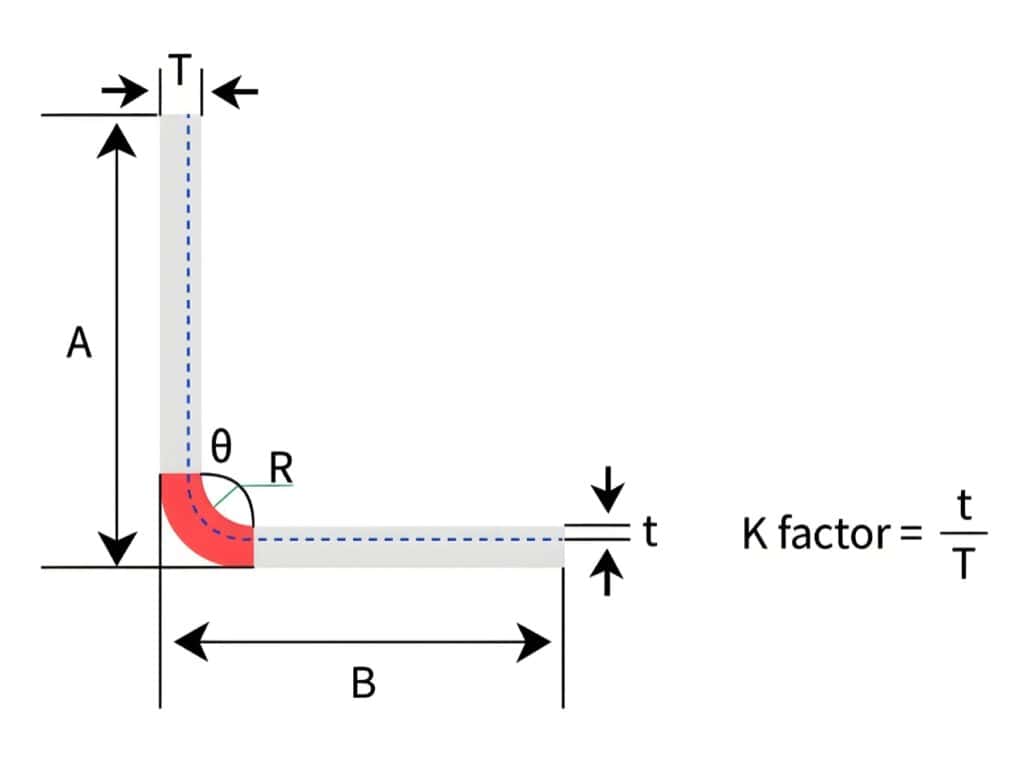
Bend Allowance vs Bend Deduction vs K-Factor: How to Calculate Sheet Metal Flat Patterns (With Examples)
Post Your Review
Share Your Thoughts And Feelings With Others