


Francis Pan
Francis Pan is the Foreign Trade Manager of RAYMAX, with over 10 years of experience in sheet metal fabrication equipment and CNC machinery. He has worked closely with manufacturers worldwide on press brakes, fiber laser cutting machines, fiber laser welding machines, and practical production-oriented metal processing solutions.
Top Guidelines
-1024x768.jpg)
-1024x768.jpg)
-1024x768.jpg)
-1-1024x768.jpg)
Table Of Contents
Stay in the the loop
Subscribe To Our Newsletter
Quick Answer
When selecting a clamping system for high-mix production, the first consideration should be how many tool changes are required per day. Frequent tool changes result in frequent machine downtime, which increases downtime costs. The higher the downtime costs, the easier it is to calculate a clear ROI for a quick-clamping or hydraulic clamping system.
The key to determining whether a clamping system is worth the investment lies not in its price, but in how much time you waste annually due to slow tool changes—this wasted time directly impacts your production value.
30-Second Decision Chart
|
On-Site conditions |
Direct conclusions |
|---|---|
|
0–1 tool change per day, or only a few times per week |
A manual clamping system is sufficient |
|
2–5 tool changes per day |
Prioritize a quick-clamping system |
|
More than 6 tool changes per day; long press brake beds, heavy tooling, and multi-shift production |
Prioritize a hydraulic clamping system |
|
Long or heavy tooling requiring multiple operators to handle |
Prioritize a hydraulic clamping system or a high-grade quick-clamping system |
|
Future plans to implement robots; requires automatic tool change and offline programming |
Prioritize a hydraulic clamping system or an automatic clamping system |
|
The backgauge, ram, and crowning on the old machine are unstable |
First address the stability of the entire machine, then consider which clamping system to choose |
|
First standardize the tooling system, then consider which clamping system to choose |
Inconsistent tooling standards |
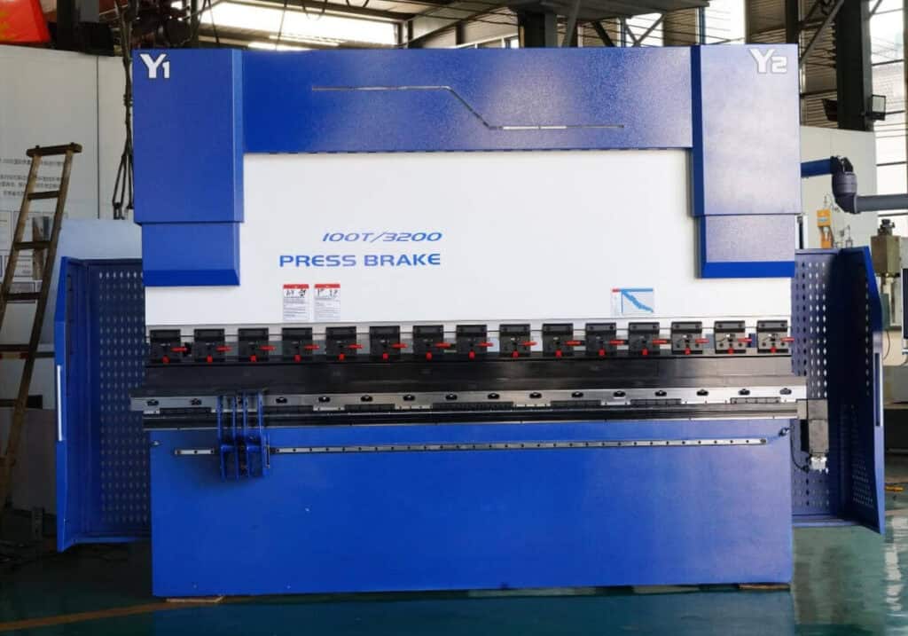
For shops with frequent tool changes, a properly configured high-mix CNC press brake should be evaluated together with tooling, clamping, backgauge, crowning and control system options.
.jpg)
Why does the clamping method directly determine production capacity in high-mix production?
First, we need to understand what “high-mix production” refers to.
Second, we need to clarify two industry concepts related to production capacity: green time and red time.
Therefore, the goal of high-mix production is to minimize red time as much as possible and maximize green time.
Finally, let’s look at a real-world example on the shop floor to see how clamping methods affect production capacity:
Many factories value manual clamping systems for their low cost, but in reality, this merely shifts the initial savings in procurement costs to later downtime costs. In production with infrequent tool changes, manual clamping systems are indeed cost-effective; however, in high-mix production with frequent tool changes, they actually hinder productivity. Let’s run the numbers below.
How to Calculate the Cost of Tool Change Time? ROI Calculation Examples for Quick-Clamping Systems and Hydraulic Clamping Systems
The ROI formula for a quick-clamping system is: minutes saved per tool change × number of tool changes per day × total hourly cost, which equals the daily value of recovered production capacity. Convert this result to annual value, then divide the clamping system’s purchase cost by the annual value to calculate the approximate payback period.
Step 1: Use two tiers for the total hourly cost—don’t just list a single figure.
|
Cost basis |
What is included |
Applicable to |
|---|---|---|
|
Conservative Estimate: $35–50 per hour |
Labor costs + basic machine time cost |
Small and medium-sized factories conducting conservative ROI calculations |
|
Comprehensive Estimate: $100–180 per hour |
Equipment depreciation, facility rent, electricity costs, production scheduling losses, opportunity costs |
Factories in Europe and the U.S., contract manufacturers, and workshops with tight production schedules |
When an operator spends more than ten minutes performing a tool change, what is lost is not just the wages for those ten minutes, but the production capacity of the entire press brake for that period.
Step 2: Formula
This calculation estimates the recovered “green light” time of the machine after the tool change time is reduced; it does not equal the final profit earned. Only when the workshop has sufficient orders and can fully utilize this freed-up time for production will this time be converted into actual production value.
Time Saved per Tool Change = Manual Tool Change Time − Post-Upgrade Tool Change Time
Annual Recovered Green-Time Hours = Minutes Saved per Tool Change × Number of Tool Changes/Day × Working Days/Year ÷ 60
Annual Recovered Value = Annual Recovered Green-Time Hours × Comprehensive Hourly Cost
Payback Period = Clamping System Purchase Price ÷ Annual Recovered Value
These four formulas help us determine whether a clamping system is worth purchasing in the vast majority of cases. When preparing a full machine budget, the quick-change clamping system cost should be evaluated together with controller grade, tooling standards, crowning, delivery terms, and installation costs. The first step on-site is to measure the time required for a tool change and the number of tool changes to provide an accurate basis for subsequent ROI calculations.
To help you better understand how to perform these calculations, we provide three sample calculations below, all based on the following parameters:
Example 1 | 1 Tool Change Per Day:
Assuming each manual tool change takes 20 minutes, upgrading to a quick-clamping system reduces the time per change to 5 minutes, resulting in a savings of 15 minutes per change. Calculated based on one tool change per day over 250 working days per year:

As we can see, with only one tool change per day, the ROI of the quick-clamping system is indeed not very high. If your budget is limited, we recommend allocating those funds to tooling, the backgauge, or the control system first.
Example 2 | 3 Tool Changes Per Day:
All other conditions from Example 1 remain the same; the number of daily tool changes is increased from 1 to 3:

If the upgrade cost is lower than the annual recovered value, a shop with three tool changes per day can generally achieve payback in about one year.
Example 3 | 8 Tool Changes Per Day:
Assuming each manual tool change takes 20 minutes, upgrading to a hydraulic clamping system reduces the time per change to 2–3 minutes, resulting in a savings of approximately 17 minutes per change. Based on 8 tool changes per day and 250 working days per year:
.jpg)
Using a conservative rate of $35 per hour:
.jpg)
Using a full-cost rate of $120 per hour:
.jpg)
We can see that when performing 8 tool changes per day, the value of the hydraulic clamping system extends beyond simply reducing tool change time. It also minimizes issues arising from frequent tool changes—such as inconsistent manual clamping, fluctuations in quality of the first part, and repeated adjustment—while helping the workshop recover a significant amount of downtime and convert it into actual production time.
ROI Summary Table
|
Number of tool changes per day |
Savings per session |
Annual green-time hours |
Assessment |
|---|---|---|---|
|
1 time |
15 minutes |
62.5 hours |
Slow return on investment; carefully consider whether an upgrade is necessary |
|
3 times |
15 minutes |
187.5 hours |
Consider evaluating a quick-clamping system |
|
5 times |
15 minutes |
312.5 hours |
Strongly recommend a quick-clamping system |
|
8 times |
17 minutes |
567 hours |
Give priority to a hydraulic clamping system |
|
10 or more times |
17 minutes or more |
700 hours or more |
Based on the configuration of the high-mix production line |
Manual vs Quick vs Hydraulic Clamp: What Are the Key Differences Between These Three Press Brake Clamping Systems?
The real difference between manual, quick-clamping, and hydraulic clamping systems lies not in which one provides the tightest grip, but in the speed of tool change and the uniformity of clamping force along the entire length. The former determines production capacity, while the latter determines precision. If you need a basic explanation of clamp types, tooling compatibility, and faster tool changeover options before calculating ROI, start with this press brake clamping system guide.
Key Comparison Table
|
Comparison criteria |
Manual clamps (bolts/clamping plates) |
Quick clamp (manual lever / pneumatic) |
Hydraulic clamps |
|---|---|---|---|
|
Tool change time (complete upper punch set) |
30–45 minutes |
3–10 minutes |
Tens of seconds to several minutes |
|
Tool loading method |
Most require lateral insertion |
Mostly vertical loading and unloading in front of the press brake |
Vertical loading and unloading at the front of the machine; automatic positioning or centralized clamping can be achieved depending on the system configuration. |
|
Uniformity of clamping force along full length |
Operator-dependent; noticeable deviation may occur between the two ends of a long press brake bed. |
Moderate; pneumatic clamping is more uniform than manual lever clamping |
More uniform distribution, making it easier to achieve consistency along the entire length |
|
Load capacity |
Low |
Medium (higher for pneumatic) |
High |
|
Repeatability of positioning |
Susceptible to operator fatigue |
Fairly stable |
Most stable, suitable for high-precision, automated bending |
|
Purchasing cost |
Minimal |
Medium |
Highest |
|
Maintenance |
Virtually no maintenance required |
Low |
Requires maintenance of hydraulic lines and seals |
|
Best suited |
No need for tool changes over the long term; suitable for thin sheets and low tonnage |
Frequent tool changes; small to medium tonnage |
Long press brake bed, segmented tooling, high tonnage, multi-shift production |
Note: The tool change times, loading capacity, and clamping uniformity listed in the table are not industry standards. The actual performance of a clamping system can be affected by factors such as the brand and model of the clamp, tooling standards, and machine tonnage. For a deeper breakdown of quick clamp types, front loading methods, pneumatic options, and compatibility checks, read our guide to the press brake quick clamping system.
.jpg)
When Is It Not Worth Buying a Quick-Clamping System or Hydraulic Clamping System?
There is only one scenario in which a quick-clamping system or hydraulic clamping system is not worth purchasing: when your tool change time is not the primary factor affecting your production capacity.
However, keep in mind that while the current production model is low-mix, this does not mean it will remain so in the future. If your production conditions are gradually shifting toward high-mix, low-volume production, it is best to select a clamping system based on what your conditions will be in 18 months, rather than on current conditions.
When Should Hydraulic Clamping Be Prioritized?
When a press brake has a long bed, uses segmented tooling, and requires crowning to maintain bending accuracy, hydraulic clamping is more than a routine upgrade—it is a critical configuration for ensuring die reference lines and bending accuracy. In multi-shift operations requiring frequent tool changes, a hydraulic clamping system is an essential feature for minimizing human error.
What Causes: Why Does Improper Clamping Compromise Bending Accuracy?
Improper clamping first causes the die reference to shift, resulting in an inaccurate bend line reference; it then prevents the crowning system from accurately offsetting deformation; ultimately, this leads to substandard bending results.
Causal Chain: Uneven clamping force → Skewed reference line → Crowning system making corrections based on the skewed reference → Angle drift
When clamping force is uneven, the support provided by the upper punch varies at different positions; particularly when bending long workpieces, these minor deviations are amplified.
The crowning system is designed to counteract deformation caused by forces acting on the frame; however, if the die’s own positioning reference is already unstable, the system will make corrections based on an incorrect foundation, leading to progressively worse accuracy.
Table of Typical Symptoms
|
On-site performance |
Possible causes |
Determining direction |
|---|---|---|
|
There is angle inconsistency between workpieces in the same batch |
Uneven clamping force, operator fatigue |
Check the angular difference between the first part and the last part after a tool change |
|
Angles differ between the center and both ends of long workpieces |
Tooling reference offset + crowning corrected based on an incorrect reference |
Simultaneously check the tooling reference and crowning |
|
Segmented tooling heights are inconsistent |
Segmented tooling not level |
Check the tooling height and wear condition |
|
Surface marks and scratches are present on the surface of appearance-critical parts |
Tooling surface wear, incorrect loading/unloading procedures |
Check the anti-indentation measures and tooling surface |
|
The first part requires a repeated trial bend |
Unstable reference, inconsistencies between the program and the tooling library |
Check the tooling clamping status and process management |
The clamping system is the first step in ensuring machining accuracy. If the initial positioning is not done correctly, even the most precise crowning and measurements later on will not be able to compensate for the loss of accuracy. Clamping is only one part of the accuracy chain; for a full process check, use this guide to improve press brake bending consistency.
How Should High-Mix Production Inform the Selection of Press Brake Configuration?
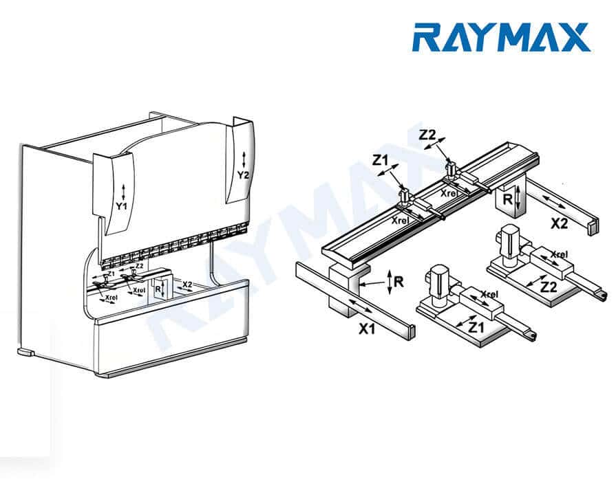
When purchasing press brakes for high-mix production workshops, one must not focus solely on the two basic parameters of “tonnage” and “length.” Key configurations such as the clamping system, segmented tooling, number of backgauge axes, control system, and crowning must all be taken into account. Otherwise, while the machine may be capable of performing bends, it may not be suitable for the demands of “high-mix, low-volume production.”
.jpg)
When you’re purchasing a press brake for high-mix production, Raymax won’t just ask about tonnage and length—we’ll also confirm the material, sheet thickness, maximum workpiece length, tool change frequency, tooling system, number of backgauge axes, and whether you plan to upgrade to automated bending in the future, to help you select the appropriate configuration.
Ready To Upgrade Your Metal Fabrication Line?
Email Us For A Free Consultation.
Checklist: What operating conditions must be confirmed before purchasing?
Before requesting a quote, clearly specify the tool change frequency, tooling standards, machine bed length, and whether you plan to automate bending in the future. This will help avoid most mistakes in clamping system selection and ROI calculations.
The following questions must be fully answered and provided to the supplier:
After receiving your list of questions, the supplier should at least be able to provide the following configuration recommendations:
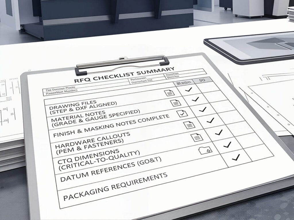
Tonnage, length, control system, number of backgauge axes, clamping system type, punch-and-die setup, crowning system, safety system, sheet follower system, estimated tool change efficiency, and ROI estimate. If you are preparing an inquiry, use this press brake RFQ checklist to organize material, thickness, bending length, tooling, clamping, and production requirements before requesting a quote.
Troubleshooting: How to troubleshoot slow tool changes, angle drift, and poor clamping?
The primary causes of slow tool changes and unstable angle accuracy are usually not machine malfunctions, but rather the clamping system and on-site operations failing to keep pace with the demands of high-mix production.
Troubleshooting Checklist
|
Symptoms |
Most likely causes |
Action plan |
|---|---|---|
|
Tool changes are too slow |
Long setup times for bolt clamping and tooling alignment |
Upgrade to a quick-clamping system and implement tool numbering |
|
The first part after a tool change always requires multiple trial runs |
Unstable clamping reference; program not linked to the tooling |
Standardize the tooling library, program library, and first-part verification process |
|
Angle drift within the same batch |
Inconsistent clamping force; operator fatigue; incorrect crowning settings |
Check the clamping status of the clamping system and verify the crowning settings |
|
Angle inconsistency between the ends and the middle of long parts |
Insufficient crowning or unstable clamping reference |
Check both crowning and clamping force |
|
Misalignment of segmented tooling assemblies |
Uneven tooling heights; tooling wear; tooling not positioned correctly |
Check the tooling condition |
|
Inadequate clamping, slippage |
Mismatched interfaces; insufficient clamping force; component wear |
Verify tooling standards and clamping system specifications |
|
Dents on appearance-critical parts |
Tooling surface wear; incorrect loading/unloading procedures |
Review the anti-indentation measures and inspect the tooling surface condition |
Quick-clamping systems can speed up tool changes, while hydraulic clamping systems can improve clamping consistency during frequent tool changes. However, if on-site management is disorganized, neither quick-clamping systems nor hydraulic clamping systems can replace standard operating procedures.
Final Verdict: Which Press Brake Clamp Fits Your Changeover Rate?
Choosing a clamping system essentially means choosing your tool change speed.
If your press brake spends a significant amount of time on daily tool changes, send Raymax your materials, sheet thickness, maximum bending length, number of daily tool changes, tool change time, workpiece drawings, batch size, target production capacity, and any future plans for automated bending. We will help you build a custom press brake configuration and calculate the payback period based on your changeover rate.
Ready To Upgrade Your Metal Fabrication Line?
Email Us For A Free Consultation.
Frequently Asked Questions (FAQs)
Related Blog
The Ultimate Guide to Press Brake Safety Devices and Guidelines for 2025
One Article to Master CNC Press Brakes: Types, Workflow, Structure & Buying Tips
How to Spec a Press Brake for Tolerance: Angle, Flange Length, Crowning, Backgauge & Acceptance Checklist
NC vs CNC Press Brake: Key Differences, Selection Guide, and Industry Applications
What is a 4 Axis Press Brake? Configuration, Advantages and Uses analysis
Press Brake Guarding Systems & Requirements: OSHA & ANSI Safety Guide
Press Brake Bending Accuracy Checklist: 10 Quantified Factors to Inspect
Master the Machine: Full Press Brake Structural Components Guide
-1024x768.jpg)
Press Brake Backgauge Accuracy Troubleshooting: How to Diagnose Flange Length Errors
CNC press brake axis: Mastering Configurations from 2-Axis to 8+1 for Pro Results
Proper setup steps for Press brakes and analysis of common calibration issues
Press Brake for Stainless Steel: Tonnage, V-Die Selection, Springback & Surface Protection
Post Your Review
Share Your Thoughts And Feelings With Others